homematic IP DRI32 32チャンネル有線入力モジュール

パッケージ内容
- 有線入力モジュール x 1 – 32 チャンネル
- バス接続ケーブル×1
- バス用ブラインドプラグ×1
- ユーザーマニュアル x 1
このマニュアルに関する情報
Homematic IP Wiredデバイスをご使用になる前に、このマニュアルをよくお読みください。このマニュアルは、後で参照できるように保管してください。デバイスを他の人に譲渡する場合は、このマニュアルを読んでもらうように依頼してください。
使用される記号
 これは危険を示しています。
 このセクションには、重要な追加情報が含まれています。
危険情報
- 本来の目的以外でのご使用、不適切な取り扱い、または危険に関する警告を遵守しなかったことに起因する損害については、当社は一切の責任を負いません。これらの場合、すべての保証請求は無効となります。また、結果的な損害についても当社は一切の責任を負いません。
- 目に見える損傷や故障がある場合は、デバイスを使用しないでください。ご不明な点がある場合は、資格のある専門家にデバイスの点検を依頼してください。
- 安全性およびライセンス上の理由 (CE) により、デバイスの無許可の変換および/または変更は許可されていません。
- このデバイスはおもちゃではありません。子供が遊ばないようにしてください。
- プラスチックフィルム、ビニール袋、発泡スチロール部品などはお子様にとって危険です。梱包材はお子様の手の届かないところに保管し、すぐに廃棄してください。
- 柔らかく清潔な糸くずの出ない布でデバイスを拭いてください。溶剤を含む洗剤は使用しないでください。
- 本製品を湿気、振動、直射日光などの継続的な熱放射、極度の寒冷、または機械的な負荷にさらさないでください。本製品は屋内でのみ操作してください。
- DIN EN 50130-4 に準拠した警報技術アプリケーションでデバイスを使用する場合は、主電源障害の可能性に備えて適切な無停電電源装置 (UPS) と組み合わせてのみ使用してください。
- 設置手順に従わない場合、火災や感電の危険が生じる可能性があります。本装置は建物設備の一部です。計画および設置の際は、関連する国の規格および指令を遵守してください。
- 本装置はHomematic IP有線バスでのみ動作します。Homematic IP有線バスはSELV電源回路です。主電源電圧はtag建物設備とHomematic IP有線バスの電源ケーブルは別々に配線する必要があります。設置ボックスや接続箱内で、電源ケーブルとHomematic IP有線バスのケーブルを共通配線することは許可されていません。建物設備からHomematic IP有線バスへの電源供給には、常に必要な絶縁を確保する必要があります。
- 安全な操作のために、デバイスはVDE 0603、DIN 43871(低電圧)規格に準拠した回路配電盤に設置する必要があります。tagサブ配電盤(NSUV)など)、DIN 18015-xに準拠した機器です。本機器は、DIN EN 60715に準拠した取り付けレール(トップハットレール、DINレール)に設置する必要があります。設置および配線は、VDE 0100(VDE 0100-410、VDE 0100-510)に準拠して行う必要があります。エネルギー供給業者の技術接続規則(TAB)の規定を遵守する必要があります。
- デバイスの端子に接続するときは、許容されるケーブルの種類と導体の断面積を守ってください。
- このデバイスは住宅環境での使用にのみ適しています。
一般的なシステム情報
- このデバイスはHomematic IPスマートホームシステムの一部であり、Homematic IPを介して通信します。操作にはHomematic IP有線アクセスポイントへの接続が必要です。システム要件と設置計画に関する詳細は、Homematic IP有線システムのマニュアルをご覧ください。
- すべての技術文書とアップデートは以下からご覧いただけます。 www.homematic-ip.com.
機能とデバイスオーバーview
- Homematic IP有線入力モジュール – 32チャンネルは、配電盤のDINレールに簡単に設置できます。32入力は、複数のスイッチや押しボタンを接続できます。ampその後、ペアになった Homematic IP 有線スイッチングまたは調光アクチュエータを介して、照明器具またはその他の照明システムを切り替えたり、調光したりできるようになります。
- また、NC または NO 接点などを監視するために、モジュールの個々の入力をセンサー入力として設定することもできます。
- このデバイスは、主電源ボリュームの使用のための特別な機能を提供しますtagプッシュボタンやスイッチなどの入力部で「腐食保護」を有効にすると、腐食やボタン/スイッチの機能低下を防ぐことができます。この機能により、プッシュボタン/スイッチが押された際に、短時間、高電流が流れます。この電流パルスによって腐食を防止します。この機能はデフォルト設定では無効になっており、チャンネルごとに個別に有効にすることができます。
デバイスオーバーview
- A) システムボタン(デバイスLED)
- B) チャンネルボタン
- C) 選択ボタン
- D) 液晶ディスプレイ
- E) バスポート1
- F) バスポート2
- G) 入力端子
- H) アース端子(GND)

表示終了view
- 1 入力が有効になっていません
 入力有効
入力有効- RXデータはバスによって受信される
- TXデータがバスに送信される
- °C 温度表示(デバイス内)
- R巻tag表示(入力または出力ボリュームtagバスターミナルにて

起動する
デバイスをコミッショニングするには、まず Homematic IP 有線アクセス ポイント (HmIPW-DRAP) をコミッショニングする必要があります。
インストール手順
- インストールを開始する前に、このセクションを完全にお読みください。
- 設置前にデバイス番号(SGTIN)と設置場所をメモしておくと、後でデバイスを識別しやすくなります。デバイス番号は、同梱のQRコードステッカーにも記載されています。
- 取り付け中は危険警告を守ってください。危険情報を参照してください。
- 入力は主電源から切断されていないtageとバスボリュームを提供するtage. 接続された押しボタン、スイッチ、またはその他のスイッチング要素は、定格電圧に対して指定されなければならない。tag少なくとも 26 V の e。
- デバイスに表示されているように、接続されている導体の絶縁剥離長さに注意してください。
- 電気安全上の理由により、Homematic IP 有線バスを接続する場合は、付属の Homematic IP 有線バス ケーブルまたは別の長さの eQ-3 Homematic IP 有線バス ケーブル (アクセサリとして入手可能) のみを使用できます。d.
- プッシュボタン/スイッチまたは通常閉/通常開の接点をデバイスに接続できます。
- 硬質ケーブルはCLに直接差し込むことができますamp 端子(プッシュイン方式)。端子上部の白い操作ボタンを押すと、フレキシブル導体を接続またはあらゆる種類の導体を切断できます。
- 家の設備に変更や作業が必要な場合(例:拡張、スイッチやソケットの挿入のバイパス)または低電圧のtagデバイスの取り付けまたは設置に配電システムを使用する場合は、次の安全上の指示に従う必要があります。
設置作業は、電気工学に関する知識と経験を有する者のみが行うことができます。*
誤ったインストールは危険にさらされる可能性があります
- あなた自身の人生、
- そして電気システムの他のユーザーの生活。
不適切な設置は、火災などによる重大な財産損害のリスクを伴います。人身傷害および財産損害に対する個人賠償責任を負うリスクがあります。
電気技師に相談してください!
- インストールに必要な専門知識:
次の専門知識は、インストール時に特に重要です。 - 使用する「5つの安全規則」:
- 主電源から切断する
- 再起動に対する安全性
- volがないか確認してくださいtage
- アースと短絡
- 隣接する通電部を覆うか遮断する
- 適切なツール、測定機器、および必要に応じて個人用保護具の選択。
- 測定結果の評価;
- 遮断状態を保護するための電気設備材料の選択。
- IP保護タイプ;
- 電気設備材料の設置;
- 供給ネットワークのタイプ (TN システム、IT システム、TT システム) とその結果の接続条件 (従来のゼロバランス、保護接地、必要な追加対策など)。
デバイスに接続するために許可されているケーブルの断面積は次のとおりです。 リジッドおよびフレキシブル ケーブル、0.25 ~ 1.5 mm²
供給量の選択tage
- 巻tagデバイスへの電源供給は、Homematic IP有線バス経由でのみ行われます。バスへの電源供給は、Homematic IP有線アクセスポイント(HmIPW-DRAP)の取扱説明書(HmIPW-DRAP)から行われます。
- 最大総消費電流は、実際に使用される入力の数から計算されます。作動入力ごとに約4mAが流れます。すべての入力をNC接点のセンサーモードで使用した場合、以下のようになります。

- 押しボタン、スイッチ、信号接点(押しボタン16個、NC接点8個、スイッチ8個)を混在させた通常のアプリケーションでは、平均消費電流が予測されます。押しボタンは操作された場合にのみ消費電流に影響を与えるため、無視できます。閉じたスイッチのみを考慮する必要があるため、ここでは平均値を使用できます(スイッチが閉じている場合は半分)。NC接点は常に閉じているため、完全に考慮する必要があります。したがって、総消費電流の例は次のようになります。

組み立てと設置
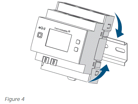
デバイスを DIN レールに取り付けるには、次の手順に従います。
- 必要に応じて配電パネルを外し、通電部分をカバーします。
- 着信HomematicIP有線バスの対応する回線を切断します。
- 配電盤からカバーを取り外します。
- デバイスを DIN レール上に置きます。

- デバイス上およびディスプレイ上の文字が読めるはずです。
- 取り付け時には、位置決めスプリングが適切にかみ合っており、デバイスがレール上にしっかりと固定されていることを確認してください。

- 接続図に従ってデバイスを配線し、設置手順に従ってください。設置手順については、6 ページを参照してください。

- バス接続ケーブルをバス ポート 1 またはバス ポート 2 に接続し、他のすべての有線デバイスをバス経由で接続します。

- バス接続 1 またはバス接続 2 が不要な場合は、付属のバス ブラインド プラグを使用します。
- 配電盤のカバーを再度取り付けます。
- 電源回路のヒューズをオンにします。
- Homematic IP 有線バスをオンにして、デバイスのペアリング モードをアクティブにします。
コントロールユニットとのペアリング
- ペアリング手順を開始する前に、このセクション全体をお読みください。
- Homematic IP Homematic IPアプリを使用して有線アクセスポイントを設定すると、システム内の有線デバイスを使用できるようになります。Homematic IPに関する詳細は、有線アクセスポイントの操作マニュアルをご覧ください。
- バスはHomematic IP有線アクセスポイント(HmIPW-DRAP)から電源を供給されます。詳細については、有線アクセスポイントの操作マニュアルを参照してください。
デバイスをコントロール センターとペアリングするには、次の手順に従います。
- Homematic IP アプリを開きます。
- ホーム画面で「…その他」をタップします。
- 「デバイスをペアリング」をタップします。
- 電源を接続します。
- ペアリングモードは3分間アクティブです。
システムボタンを短く押すと、ペアリング モードをさらに 3 分間手動で開始できます。
システムボタンの種類はデバイスによって異なります。詳しくはデバイスの取扱説明書をご覧ください。view.
- お使いのデバイスは、HomematicIPアプリに自動的に表示されます。
- デバイス番号(SGTIN)の最後の4桁をアプリに入力するか、QRコードをスキャンしてください。デバイス番号は、デバイスに付属または貼り付けられているステッカーに記載されています。
- ペアリングが完了するまで待ちます。
- ペアリングが成功すると、デバイスの LED が緑色に点灯します。
- デバイスは使用できるようになりました。
デバイスの LED が赤く点灯する場合は、もう一度フラッシュ コードと表示を試してください (11 ページ)。 - 最後に、Homematic IP アプリの指示に従います。
有線デバイスをHomematic IPワイヤレスコンポーネントと組み合わせる場合は、Homematic IP有線デバイスを(既存の)Homematic IPセントラルコントロールユニットとペアリングすることができます。これを行うには、操作マニュアルに記載されているように、Homematic IP有線アクセスポイントを(既存の)Homematic IPセントラルコントロールユニットに接続します。その後、上記の手順に従ってデバイスを接続します。
手術
セットアップ後は、デバイス上で直接簡単な操作が可能になります。

- ディスプレイをオンにします。 システム ボタンを短く押すと、バスに接続されているすべてのデバイスの LC ディスプレイがアクティブになります。
- チャンネルを選択: チャンネルボタンを短く押すと、希望のチャンネルを選択できます。ボタンを押すたびに、次のチャンネルに切り替えることができます。選択されたチャンネルは点滅するシンボルで表示されます。
- 表示値: チャネルを選択していない場合は、選択ボタンを短く押して値を切り替えます。
- バス供給量tage(V)
- デバイス内の温度(°C)
- 空のディスプレイ
Homematic IP アプリでデバイスをペアリングした場合は、デバイス設定で追加の構成を利用できます。
- チャネルを割り当てます: 個々のチャネルを目的の部屋またはソリューションに割り当てます。
工場出荷時の設定に戻す
デバイスを工場出荷時の設定に復元できます。デバイスがセントラルコントロールユニットとペアリングされている場合、設定は自動的に復元されます。デバイスがセントラルコントロールユニットとペアリングされていない場合、すべての設定が失われます。
デバイスの工場出荷時の設定を復元するには、次の手順に従います。
- システムボタンを4秒間押し続けます(図7)
- デバイスの LED がオレンジ色で速く点滅し始めます。
- システムボタンを放します。
- システムボタンを4秒間押し続けます。
- デバイスの LED が緑色に点灯します。
- システムボタンを放すと、工場出荷時の設定への復元が完了します。
- デバイスは再起動を実行します。
- デバイスの LED が赤く点灯する場合は、もう一度フラッシュ コードと表示を試してください (11 ページ)。
メンテナンスと清掃
- 本装置はメンテナンスフリーです。メンテナンスや修理は専門業者にお任せください。
- 常に主電源を切るtagデバイスの端子室で作業する前、およびデバイスの取り付けまたは取り外しを行う前に、必ずブレーカーをオフにしてください。0100 V 電源での作業は、資格を有する電気技師(VDE 230 に準拠)のみが行うことができます。
- 柔らかく、清潔で、乾いた、糸くずの出ない布を使用してデバイスを清掃してください。布は多少汚れても構いません。amp頑固な汚れを落とすには、ぬるま湯で洗い流してください。溶剤を含む洗剤は使用しないでください。プラスチック製の筐体やラベルを腐食させる可能性があります。
廃棄
 この記号は、本製品を家庭ごみ、一般廃棄物、または黄色のゴミ箱や黄色の袋に入れて廃棄してはならないことを意味します。健康と環境の保護のため、本製品および納品に含まれるすべての電子部品を、自治体の廃電気電子機器収集場所に持ち込み、適切に廃棄してください。電気電子機器の販売業者は、廃機器を無料で引き取る義務があります。分別廃棄することで、古い機器の再利用、リサイクル、その他の回収方法に貴重な貢献をすることができます。また、エンドユーザーであるお客様は、廃電気電子機器を廃棄する前に、その機器上の個人データを削除する責任があることにご注意ください。
 CE マークは、当局のみを対象とした無料の商標であり、特性の保証や保証を意味するものではありません。
- 機器に関する技術的な質問がある場合は、専門の販売店にお問い合わせください。
技術仕様
- 簡単な説明 HmIPW-DRI32
- 供給量tag24 VDC、±5 %、SELV
- 保護クラス II
- 保護等級 IP20
- 周囲温度-5–+40°C
- 重量165g
- 寸法(幅×高さ×奥行き)(4HP)72×90×69mm
- 消費電流 最大135 mA/標準2.5 mA
- 熱計算用デバイスの電力損失は最大3.25 Wです。
- スタンバイ消費電力60mW
入力
- 数量 32
- シグナルvoltag24 VDC、SELV
- 「0」信号 0~14 VDC
- 「1」信号 18~24 VDC
- 信号電流 3.2 mA(腐食保護:約125 mA)
- 信号持続時間 80 ミリ秒以上。
- 線路長200m
- ケーブルの種類と断面積:リジッドケーブルおよびフレキシブルケーブル、0.25~1.5 mm²
- 取り付け EN 60715に準拠した取り付けレール(DINレール)
変更される場合があります。
トラブルシューティング
コマンドが確認されていません
少なくとも 1 つの受信機がコマンドを確認しない場合は、失敗した送信プロセスの終了時にデバイスの LED が赤く点灯します。
フラッシュコードとディスプレイ
| フラッシュコード/ディスプレイ | 意味 | 解決 |
| オレンジ色のライト x 1 個と緑色のライト x 1 個 (有線バスをオンにした後) | テストディスプレイ | テスト表示が停止したら、続行できます。 |
| オレンジ色の短い点滅 (10 秒ごと) | ペアリングモードが有効 | アプリにデバイス番号 (SGTIN) の最後の 4 桁を入力するか、QR コードをスキャンします。 |
| オレンジ色の短い点滅 | 設定データの送信 | 送信が完了するまで待ちます。 |
| オレンジ色の短い点滅(その後緑色の点灯が続く) | 送信確認済み | 操作を続行できます。 |
| オレンジ色の短い点滅(その後赤色の点灯が続く) | 送信に失敗しました | もう一度お試しください 見る コム確認されていません、 10ページ目. |
| 6倍の長い赤の点滅 | デバイスに欠陥があります | エラー メッセージについてはアプリの表示を確認するか、販売店にお問い合わせください。 |
| オレンジ色の長短交互点滅 | ソフトウェアアップデート | 更新が完了するまで待ちます。 |
| E10 | 温度が高すぎる | 接続されている負荷を減らしてデバイスを冷却してください。 |
| E11 | アンダーボリュームtage(バスボリュームtageが低すぎる) | ボリュームをチェックtag供給し、ボリュームを調整するtag接続機器の数に応じて供給します。 |
Homematic>IP アプリを無料でダウンロードしてください!

メーカーの正規代理店
- eQ-3 AG
- MaiburgerStraße29
- 26789 Leer /ドイツ
- www.eQ-3.de
よくある質問
屋外でも使用できますか?
いいえ、デバイスは最適なパフォーマンスと寿命を確保するために屋内での使用のみを目的として設計されています。
デバイスをクリーニングするにはどうすればよいですか?
清掃には、柔らかく清潔な糸くずの出ない布をご使用ください。溶剤を含む洗剤はデバイスを損傷する可能性があるため、使用しないでください。
コマンドが確認されない問題が発生した場合はどうすればよいですか?
コマンド未確認エラーに関連するトラブルシューティング手順については、マニュアルのセクション 8.1 を参照してください。
ドキュメント / リソース
 |
homematic IP DRI32 32チャンネル有線入力モジュール [pdf] インストールガイド DRI32、DRI32 32チャンネル有線入力モジュール、DRI32、32チャンネル有線入力モジュール、有線入力モジュール、入力モジュール、モジュール |