1. はじめに
This manual provides essential information for the safe and efficient operation of your Anern 4200W Hybrid Solar Inverter. Please read this manual thoroughly before installation and use. Keep it for future reference.
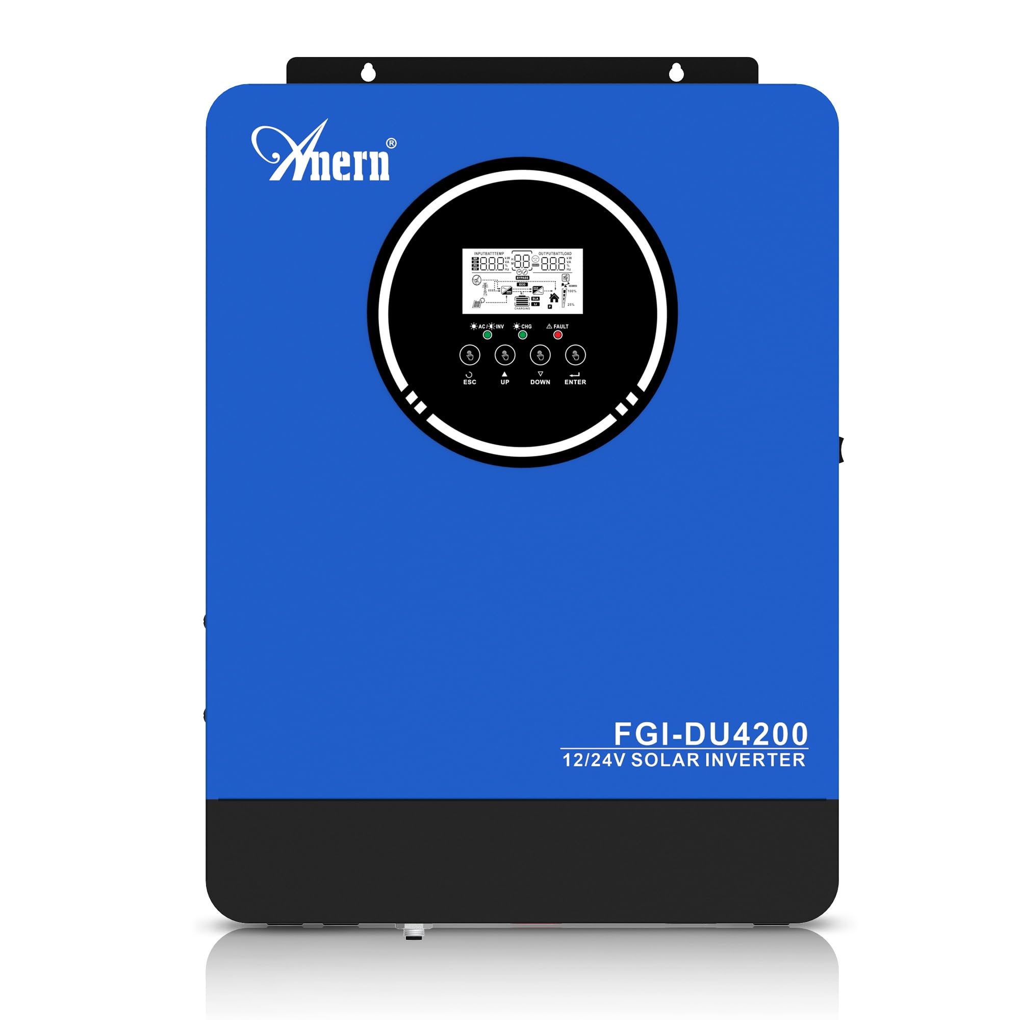
Figure 1: Anern 4200W Hybrid Solar Inverter. This image displays the main unit of the inverter, highlighting its key specifications such as 100A AC charging current, 4200W rated output power, and 500 VDC maximum PV array voltage.
2. 安全に関する注意事項
感電、火災、または怪我のリスクを軽減するために、常に次の安全上の注意事項を守ってください。
- 設置は資格を持った人が行う必要があります。
- Ensure all wiring is correctly connected and equipped with appropriate protective switches.
- インバータを分解しないでください。内部にはユーザーが修理できる部品はありません。
- インバータを雨、雪、水しぶき、その他の液体にさらさないでください。
- 過熱を防ぐために、インバータの周囲に十分な換気を確保してください。
- メンテナンスや配線を行う前に、すべての電源 (PV、バッテリー、ユーティリティ) を外してください。
3.製品オーバーview
The Anern 4200W Hybrid Solar Inverter is designed to convert DC power from solar panels and batteries into AC power for household use. It features an integrated 100A MPPT solar charge controller and supports both 12V and 24V battery systems with automatic detection.
主な特徴:
- 4200W純正弦波出力: 敏感な電子機器に安定したクリーンな電力を供給します。
- 100A MPPT Solar Charge Controller: 太陽光パネルからの電力収穫を最大化します。
- 12V/24V Battery Auto-Detection: Automatically adjusts output based on connected battery voltage.
- BMSインターフェース: Supports communication with lithium batteries for enhanced monitoring and protection.
- リアルタイム LED ディスプレイ: Shows system status, operating data, and error codes.
- Configurable Charging & Output Modes: Offers flexibility for various application needs.
- Optional WiFi/GPRS Monitoring: Remote monitoring capability (module sold separately).

Figure 2: Inverter Display and Controls. This image illustrates the inverter's LCD display, function buttons for configuration, and the optional WiFi module for remote monitoring.
4. セットアップとインストール
4.1 配線図
Refer to the electrical schematic for proper system wiring. Ensure all connections are secure and correctly polarized.

Figure 3: Electrical Schematic. This diagram shows the complete wiring for a solar inverter system, including solar panels, combiner box, DC/AC breakers, inverter, utility grid connection, and loads.
4.2バッテリー接続
The inverter supports 12V and 24V battery configurations. It automatically detects the battery voltage and adjusts its output accordingly (2300W for 12V, 4200W for 24V). For 24V systems, connect two 12V batteries in series. For 12V systems, connect batteries in parallel if increasing容量。

Figure 4: Battery Connection Options. This image illustrates how to connect batteries for 12V (parallel connection for 2300W output) and 24V (series connection for 4200W output) systems.
The inverter also supports lithium batteries and includes a BMS (Battery Management System) interface for monitoring and protection. Ensure the BMS is properly connected if using lithium batteries.

Figure 5: Communication Interfaces. This image highlights the dual communication interfaces for BMS (Battery Management System) and optional WiFi module, enabling remote monitoring and battery communication.
4.3 Startup and Shutdown Sequence
起動シーケンス:
- バッテリーを接続します。
- インバーターをオンにします。
- Activate the protective switches for PV, Utility, and Loads.
シャットダウンシーケンス:
- Deactivate the protective switches for Loads, Utility, and PV.
- インバーターの電源を切ります。
- バッテリーを外します。
Important Note: Inductive loads (e.g., motors, refrigerators) may require up to 3 times their rated power for startup. Ensure the inverter's capacity is sufficient to handle these surge loads. Exceeding the inverter's surge capacity can cause damage.
5. 操作
5.1 LCDディスプレイと設定
The inverter features an LED display that provides real-time system data and operating status. Use the function buttons below the display to navigate menus and configure settings. Settings include battery charging current, AC/solar charging priority, and charging current priority.
5.2つの充電モード
インバーターには、設定可能な 4 つの充電モードがあります。
- 太陽光の優先順位: 充電には太陽光を優先します。
- 太陽光発電のみ: 充電には太陽光エネルギーのみを使用します。
- ユーティリティの優先度: Utility grid power is prioritized for charging.
- Solar + Utility Hybrid: 充電には太陽光と公共電力を組み合わせます。
5.3 出力モード
Three output modes are available to adapt to various application needs:
- ソーラープライオリティ(SUB): Solar power is prioritized for loads.
- ユーティリティ優先(USB): Utility grid power is prioritized for loads.
- SBU: Solar, Battery, Utility priority.

Figure 6: Charging and Output Modes. This diagram visually explains the four available charging modes (Solar Charge, Utility Priority, Solar Priority, Hybrid Charge) and three load output modes (PV Priority, Utility Priority, SBU Priority).
5.4リモートモニタリング
The inverter supports remote monitoring via an optional WiFi/GPRS module (sold separately). This allows users to monitor system performance and status from a distance.
6. メンテナンス
定期的なメンテナンスにより、インバーターの最適なパフォーマンスと寿命が確保されます。
- インバーターは清潔に保ち、ほこりを取り除いてください。清掃には乾いた布を使用してください。
- 換気口がふさがれていないことを確認してください。
- すべての配線接続部の締め付け具合や腐食の兆候を定期的に確認してください。
- Monitor the battery status, especially if using lithium batteries with the BMS interface, to prevent overcharge or deep discharge.
- Inspect solar panels for dirt or damage that could reduce efficiency.
7。 トラブルシューティング
The LED display will show error codes if issues arise. Refer to the inverter's display for specific error codes to diagnose and resolve problems. Common issues and their potential solutions include:
- 電力出力なし: Check battery connections, DC/AC breakers, and inverter power switch.
- 低バッテリー容量tage: Ensure batteries are adequately charged. Check charging sources (solar, utility).
- 過負荷警告: Reduce the connected load. Inductive loads may cause temporary overloads during startup.
- 過熱: Ensure proper ventilation. Clean any dust from the inverter's vents.
- PV Input Error: ソーラーパネルの接続と電圧を確認するtage. Ensure PV array voltage は指定された範囲内(55~500V DC)です。
For persistent issues or error codes not listed, contact customer support.
8. 技術仕様
| 特徴 | 仕様 |
|---|---|
| ブランド | アナーン |
| モデル番号 | AN-FGI-DU 4200 |
| 電力 | 4200ワット |
| 出力電力 | 4500ワット |
| Max. Output Power (Watts) | 4200 |
| 出力波形 | 純粋な正弦波 |
| 電源 | ソーラーパワー、バッテリーパワー。 |
| 推奨製品用途 | 家 |
| 含まれるコンポーネント | 取扱説明書 |
| コンプライアンス | CE |
| 製品寸法 | 30 x 10 x 40 cm; 8.86 kg |
9. 保証とサポート
For warranty information and technical support, please refer to the documentation provided with your purchase or contact Anern customer service. Keep your purchase receipt as proof of purchase.