導入
This manual provides detailed instructions for the installation, operation, and maintenance of the SINOTIMER PID Temperature Controller Kit 25DA. This intelligent temperature control system is designed for precise temperature regulation in various industrial and scientific applications.
The kit includes a PID temperature controller, a 25DA Solid State Relay (SSR), a K-type screw thermocouple, and a heat sink, offering a complete solution for your temperature control needs.
キット構成
The SINOTIMER PID Temperature Controller Kit 25DA includes the following components:
- PID Temperature Controller: Digital display unit for setting and monitoring temperature.
- SSR-25DA Solid State Relay: For switching high power loads based on controller output.
- K-Type Screw Thermocouple: Temperature sensor with a 2-meter cable.
- ヒートシンク: For dissipating heat from the Solid State Relay.

画像: 上view of the PID temperature controller, SSR, K-type thermocouple, and heat sink, showing their respective dimensions.
セットアップとインストール
Proper installation is crucial for the safe and effective operation of the temperature controller. Ensure all power is disconnected before proceeding with wiring.
1. PID Controller Dimensions and Mounting

Image: Dimensions of the PID temperature controller, showing 48mm x 48mm front panel and 75mm depth.
The controller has a standard dimensional size of 45mm x 45mm for panel mounting. Ensure adequate space for ventilation and wiring connections.
2. Wiring the PID Controller
Refer to the wiring diagram on the back of the controller for terminal connections. The controller supports K, E, and J type thermocouple inputs and provides both SSR and relay control outputs.

Image: Back panel of the PID temperature controller showing terminal numbers and their functions for power, SSR output, alarm output, and thermocouple input.
- Power Supply (1, 2): Connect AC 100-240V, 50/60Hz.
- SSR Output (3, 9): Connect to the input terminals of the Solid State Relay.
- Alarm Output (7, 8): Connect to an external alarm device (AC220V/DC30V 3A resistive load).
- Thermocouple Input (11, 12): Connect the K-type thermocouple. Ensure correct polarity (+ to 12, - to 11).
3. Wiring the Solid State Relay (SSR)
The SSR-25DA is used to control the heating element. Mount the SSR onto the provided heat sink to prevent overheating. Connect the SSR to the PID controller and the heating load as shown in the diagram.

Image: Diagram illustrating the physical wiring connections between the AC power supply, SSR-25DA, DC power supply (for SSR input), and a heater example. Note the caution regarding leakage current for DC control AC applications.
- SSR Input (3, 4): Connect to the SSR output terminals (3 and 9) of the PID controller. Input voltage:3-32VDC。
- SSR Load (1, 2): Connect the AC power supply (24-380VAC) and the heating element. Terminal 1 for fire wire, Terminal 2 for zero line.
注意: For DC control AC applications, if the closed state leakage current is less than 5mA, special scenarios may not be applicable. Please exercise caution.
操作手順
The PID controller features a digital display and several buttons for setting parameters and monitoring the temperature.
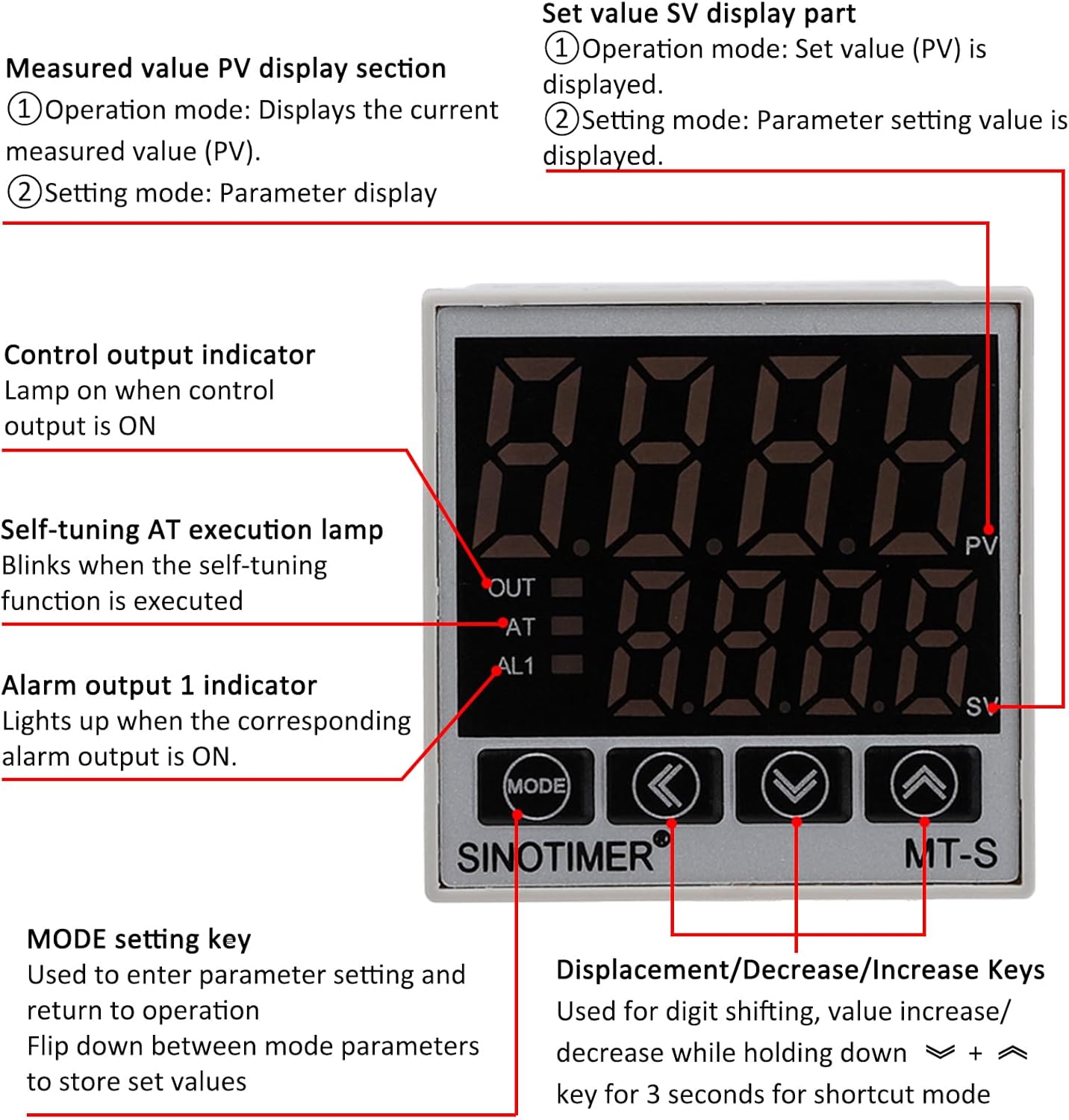
Image: Front panel of the PID temperature controller, detailing the PV (Measured Value) and SV (Setting Value) displays, control indicators (OUT, AT, AL1), and function keys (MODE, Shift, Down, Up).
表示部
- PV (Measured Value) Display: 現在の測定温度を表示します。
- SV (Setting Value) Display: Shows the set temperature or parameter setting value.
- アウトインジケータ: Lights up when the control output is ON.
- ATインジケーター: Blinks when the self-tuning (Auto-Tune) function is active.
- AL1 Indicator: Lights up when the corresponding alarm output is ON.
コントロールキー
- モードキー: Used to enter parameter settings and return to operation. Press to flip down between mode parameters and store set values.
- Shift Key (<): Used for digit shifting during value adjustment.
- Decrease Key (v): Decreases the setting value. Holding for 3 seconds may activate a shortcut mode.
- Increase Key (^): Increases the setting value. Holding for 3 seconds may activate a shortcut mode.
設定温度
- In normal operation mode, the SV display shows the set temperature.
- 使用 Decrease (v) そして Increase (^) キーを押して希望の温度を調整します。
- の Shift (<) key can be used to move the cursor to adjust specific digits.
- The controller will automatically save the new set value after a short period of inactivity or by pressing the モード 鍵。
Parameter Settings and Auto-Tune
To access advanced parameters or initiate the auto-tune function, refer to the detailed programming guide (usually provided separately or accessible via specific key combinations). The AT indicator will blink during auto-tuning.
The controller supports both Celsius (℃) and Fahrenheit (℉) display. This setting can typically be changed within the parameter menu.
メンテナンス
The SINOTIMER PID Temperature Controller Kit is designed for reliable operation with minimal maintenance. Follow these guidelines to ensure longevity:
- クリーニング: コントローラーのディスプレイとボタンは、柔らかく乾いた布で拭いて清潔に保ってください。研磨剤入りの洗剤や溶剤の使用は避けてください。
- 環境: Ensure the operating environment is within the specified temperature and humidity ranges. Avoid excessive dust, moisture, and corrosive gases.
- 接続: Periodically check all wiring connections for tightness and signs of wear or corrosion. Ensure the heat sink for the SSR is free from obstructions and dust to maintain efficient cooling.
- 熱電対: Inspect the thermocouple for physical damage or signs of degradation. Replace if necessary to maintain accurate temperature readings.
トラブルシューティング
If you encounter issues with your PID Temperature Controller Kit, refer to the following common problems and solutions:
| 問題 | 考えられる原因 | 解決 |
|---|---|---|
| コントローラの電源が入らない。 | 電源が供給されていないか、配線が間違っています。 | Check power connections (terminals 1 & 2). Ensure AC 100-240V is supplied. |
| Temperature reading is inaccurate or "HHHH" / "LLLL" displayed. | Thermocouple disconnected, reversed polarity, or faulty. | Verify thermocouple connection (terminals 11 & 12) and polarity. Replace thermocouple if damaged. |
| Heater does not turn on/off. | SSR wiring incorrect, SSR faulty, or controller output issue. | Check SSR input wiring from controller (terminals 3 & 9). Verify SSR load wiring (terminals 1 & 2). Test SSR functionality if possible. Ensure controller output (OUT indicator) is active. |
| Controller not maintaining set temperature. | Incorrect PID parameters or insufficient heating/cooling capacity. | Perform auto-tune (AT function) to optimize PID parameters. Ensure the heating element is adequately sized for the application. |
これらの解決策を試しても問題が解決しない場合は、カスタマー サポートにお問い合わせください。
仕様
- モデル: SINOTIMER MT-S (PID Temperature Controller)
- 電源: AC 100-240V、50/60Hz
- 入力タイプ: K, E, J Thermocouple (K-type screw thermocouple included)
- 温度範囲: 0-999℃ / ℉ (Display)
- 制御出力: Relay / SSR (25DA SSR included)
- アラーム出力: 1 Alarm Relay Output (AC220V/DC30V 3A Resistive load) NO/NC
- コントローラーの寸法: 48mm x 48mm (Front Panel), 75mm (Depth)
- SSR Model: FOTEK SSR-25 DA
- SSR入力ボリュームtage: 3~32VDC
- SSR 負荷量tage: 24-380VAC
- 熱電対タイプ: K-Type Screw, 2M length
- 材料: Flame Retardant ABC material
- 商品の重量: 約12.7オンス(キット全体)
- パッケージ寸法: 5.28 x 4.21 x 3.11インチ
保証とサポート
For warranty information and technical support, please refer to the documentation provided with your purchase or contact SINOTIMER customer service directly. Keep your purchase receipt for warranty claims.
Manufacturer: SINOTIMER