1. はじめに
Thank you for choosing the Irfora T58B Digital Multimeter. This instrument is a handheld, true RMS digital multimeter designed for accurate measurement of AC/DC voltage, AC/DC current, frequency, resistance, capacitance, and diodes. It is a versatile tool for solving industrial and household electrical problems, suitable for both DIY enthusiasts and professionals.
Please read this manual thoroughly before use to ensure safe and proper operation. Keep this manual for future reference.
2. 安全情報
警告: 感電やけがを避け、メーターやテスト対象機器の損傷を防ぐために、次の安全規則を守ってください。
- メーターが測定に対して正しい機能と範囲内にあることを常に確認してください。
- 定格容量を超えて塗布しないでくださいtage、メーターにマークされているように、端子間、または端子とアース間。
- ボリュームを扱うときは注意してくださいtag30V AC RMS、42Vピーク、または60V DCを超える電圧。このような電圧はtag感電の危険があります。
- 電流測定を行う前に、メーターのヒューズが破損していないこと、テスト リードが正しい入力ジャックに接続されていることを確認してください。
- 機能または範囲を変更する前に、テスト リード線を回路から取り外します。
- メーターが損傷しているように見える場合、またはテスト リード線の絶縁が損なわれている場合は、メーターを使用しないでください。
- 誤った読み取りを避けるため、電池残量低下インジケーターが表示されたらすぐに電池を交換してください。
- 地域および国の安全規定を遵守してください。
3.製品オーバーview
The Irfora T58B Digital Multimeter features a robust design and a clear LCD display for easy readings.
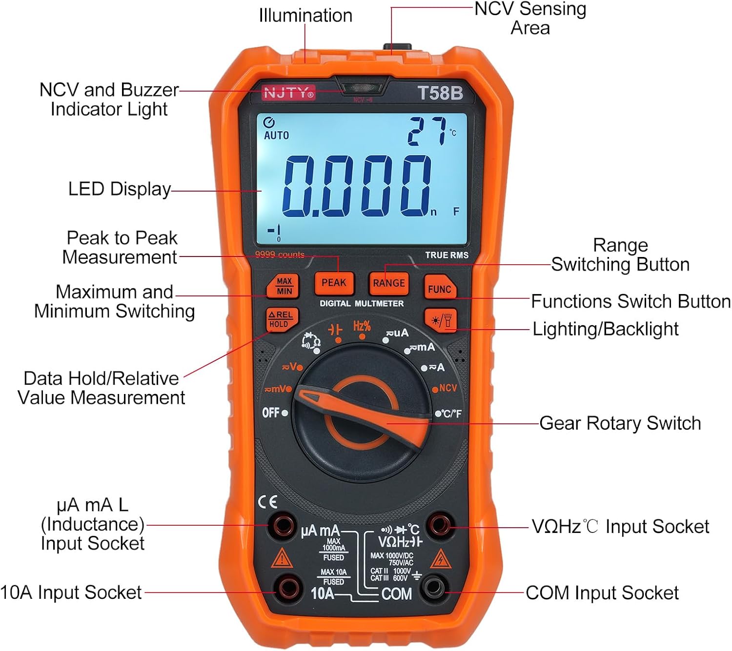
図3.1: フロント view of the Irfora T58B Digital Multimeter with labeled components. Key features include the LED Display, NCV and Buzzer Indicator Light, Gear Rotary Switch, Input Sockets, and various function buttons.

図3.2: Dimensions of the Irfora T58B Digital Multimeter. The device measures approximately 187mm (7.36in) in height, 95mm (3.74in) in width, and 55mm (2.16in) in depth.

図3.3: 後方 view of the multimeter showing the 90-degree adjustable support stand and integrated storage slots for test leads, designed for convenience and protection.

図3.4: 以上view of the Irfora T58B Digital Multimeter's capabilities, including 9999 counts display, and measurement of current, resistance, capacitance, temperature, and frequency.
主な特徴:
- 9999 Counts LCD Digital Display with Backlight
- 真の実効値測定
- 非接触巻tage (NCV) 検出
- 自動電源オフ
- Data Hold and Relative Value Measurement
- Flashlight Function for low-light conditions
- AC/DC Volを測定tage, AC/DC Current, Resistance, Capacitance, Frequency, and Temperature
- ダイオードと導通テスト
4. セットアップ
4.1. バッテリーの取り付け
The Irfora T58B Multimeter requires 3 x 1.5V AAA batteries (not included). To install or replace batteries:
- マルチメーターの電源がオフになっていることを確認し、すべてのテストリード線を入力端子から取り外します。
- メーターの背面にある電池ボックスのカバーを見つけます。
- ドライバーを使用して、バッテリー カバーを固定しているネジを緩めます。
- Remove the cover and insert the 3 AAA batteries, observing the correct polarity (+ and -).
- 電池カバーを元に戻し、ネジを締めます。
注記: 液漏れを防ぐため、メーターを長期間使用しない場合は電池を取り外してください。
4.2. テストリードの接続
Always connect the black test lead to the "COM" (Common) input jack. Connect the red test lead to the appropriate input jack based on the measurement type:
- ボリューム用tage, Resistance, Capacitance, Frequency, Diode, and Temperature measurements: Connect the red lead to the "VΩHz°C" jack.
- For Current measurements (up to 600mA): Connect the red lead to the "µA mA" jack.
- For High Current measurements (up to 10A): Connect the red lead to the "10A" jack.
Ensure test leads are fully inserted into the jacks before use.
5. 操作手順
To operate the multimeter, turn the Gear Rotary Switch to the desired function. The meter will automatically select the appropriate range in most modes (AUTO function).
5.1. AC / DC Voltag測定
- ロータリースイッチを「V~」(AC Voltage) または「V-」(DC Voltage) 位置。
- Connect the black test lead to the "COM" jack and the red test lead to the "VΩHz°C" jack.
- テストプローブを回路のポイントに接触させて、tage を測定する必要があります。
- 巻を読むtagLCDディスプレイのe値。
5.2. AC/DC 電流測定
注意: メーターをボリュームに並列に接続しないでくださいtag電流測定時は電源を切ってください。ヒューズが切れたり、メーターが損傷したりする可能性があります。
- Turn the rotary switch to the "µA mA" or "A" position for AC or DC current. Use the "FUNC" button to switch between AC and DC if necessary.
- Connect the black test lead to the "COM" jack. Connect the red test lead to the "µA mA" jack for currents up to 600mA, or to the "10A" jack for currents up to 10A.
- 電流を測定する回路を開き、メーターを負荷と直列に接続します。
- LCDディスプレイで現在の値を読み取ります。
5.3.抵抗測定
- ロータリースイッチを「Ω」の位置に回します。
- Connect the black test lead to "COM" and the red test lead to "VΩHz°C".
- 抵抗を測定する前に、回路の電源が切れていることを確認してください。
- Touch the test probes across the component or circuit where resistance is to be measured.
- LCD ディスプレイで抵抗値を読み取ります。
5.4. 静電容量測定
- Turn the rotary switch to the "Capacitance" position (often shared with other functions, use FUNC button if needed).
- Connect the black test lead to "COM" and the red test lead to "VΩHz°C".
- Discharge the capacitor completely before measurement to avoid damage to the meter.
- テストプローブをコンデンサの端子に接触させます。
- LCD ディスプレイの静電容量値を読み取ります。
5.5.周波数測定
- ロータリースイッチを「Hz」の位置に回します。
- Connect the black test lead to "COM" and the red test lead to "VΩHz°C".
- Touch the test probes across the circuit where frequency is to be measured.
- LCD ディスプレイ上の周波数値を読み取ります。
5.6. ダイオードテストと導通
- Turn the rotary switch to the "Diode/Continuity" position. Use the "FUNC" button to toggle between diode test and continuity.
- Connect the black test lead to "COM" and the red test lead to "VΩHz°C".
- For Diode Test: Place the red probe on the anode and the black probe on the cathode. The display will show the forward voltag電圧降下。プローブを逆向きに差し込むと、正常なダイオードの場合はディスプレイに「OL」(オープンループ)と表示されるはずです。
- For Continuity Test: Touch the probes to the circuit points. If resistance is below approximately 50Ω, the buzzer will sound, indicating continuity.
5.7.温度測定
- ロータリースイッチを「°C/°F」の位置に回します。
- Connect the thermocouple (included) to the "VΩHz°C" and "COM" jacks, observing polarity.
- Place the thermocouple tip on the object or area where temperature is to be measured.
- Read the temperature value on the LCD display. Use the "FUNC" button to switch between Celsius and Fahrenheit.
5.8.非接触Voltage (NCV) 検出

図5.1: Demonstrating NCV (Non-Contact Voltage) detection. The meter's top is placed near an AC voltage source, and the signal strength indicator lights up, accompanied by an audible alarm.
- ロータリースイッチを「NCV」の位置に回します。
- Place the top of the meter (NCV sensing area) close to the conductor or outlet you suspect has AC voltage.
- ACvolの場合tage is detected, the corresponding signal strength indicator (low-yellow, high-red) will light up, and the buzzer will emit different frequency alarms based on signal strength.
5.9. バックライトとフラッシュライト
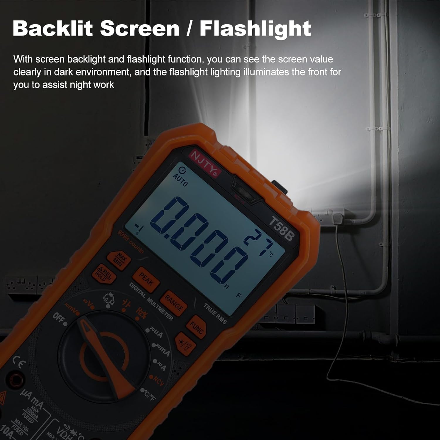
図5.2: The multimeter's backlit screen and integrated flashlight illuminate the display and work area, enhancing visibility in dark environments.
Press the "Lighting/Backlight" button (often marked with a light bulb icon) to turn on the display backlight. Press and hold the same button to activate the flashlight located at the top of the meter. Press again to turn off.
5.10. 自動電源オフ

図5.3: The multimeter features an automatic shutdown function, turning off after approximately 15 minutes of inactivity to conserve battery life.
The multimeter will automatically power off after approximately 15 minutes of inactivity to conserve battery life. An audible voice prompt will sound before shutdown. To restart the meter, press any button or turn the rotary switch.
6. メンテナンス
6.1. 清掃
広告でメーターを拭くamp 布と中性洗剤を使用してください。研磨剤や溶剤は使用しないでください。入力端子を汚れや湿気から守ってください。
6.2. バッテリーの交換
When the low battery indicator appears on the display, replace the batteries as described in Section 4.1. Prompt battery replacement ensures accurate readings.
6.3.ヒューズの交換
メーターが電流を測定できない場合は、ヒューズが切れている可能性があります。ヒューズを交換するには、以下の手順に従ってください。
- マルチメーターの電源がオフになっていることを確認し、すべてのテストリードを外します。
- セクション 4.1 の説明に従って、バッテリー コンパートメント カバーを開きます。
- 古いヒューズを慎重に取り外します。
- Replace with a fuse of the same type and rating:
- For µA mA input: F 600mA/250V
- For 10A input: F 10A/250V
- 電池カバーを元に戻し、ネジを締めます。
7。 トラブルシューティング
| 問題 | 考えられる原因 | 解決 |
|---|---|---|
| メーターの電源が入りません。 | 電池が切れているか、正しく取り付けられていない。 | Check battery polarity and replace batteries if necessary (Section 4.1). |
| No reading or "OL" displayed during measurement. | Incorrect range, open circuit, or blown fuse (for current). | Ensure correct function/range. Check test lead connections. For current, check and replace fuse (Section 6.3). Verify circuit continuity. |
| 不正確な測定値。 | バッテリー残量が少ない、接続が正しくない、または外部からの干渉が発生しています。 | Replace batteries. Recheck test lead connections. Move away from strong electromagnetic fields. |
| Buzzer does not sound during continuity test. | Circuit resistance is too high. | Ensure resistance is below approximately 50Ω for continuity indication. |
これらの解決策を試しても問題が解決しない場合は、カスタマー サポートにお問い合わせください。
8. 仕様
The following specifications are for the Irfora T58B Digital Multimeter:
一般仕様:
- Display: 9999 Counts LCD display
- Safety Rating: CAT III 600V, CAT II 1000V
- Pollution Grade: 2
- Working Height: Under 2000m
- Working Temperature: 0-40°C (<80%RH, not considered <10°C)
- Storage Temperature: -10~60°C (<80%RH, remove battery)
- Test/Calibration Ambient Temperature: 20°C ± 2°C
- 最大巻tage between Measurement End and Ground: 1000V DC or 750V AC
- ヒューズ保護:
- For µA mA input: F 600mA/250V
- For 10A input: F 10A/250V
- Conversion Rate: Approximately 3 readings/second
- Overload Display: "OL"
- Power Supply: 3 * 1.5V AAA batteries (Not included)
- 商品サイズ:187 * 95 * 55mm / 7.36 * 3.74 * 2.16インチ
- 商品重量: 331g / 11.67オンス
測定範囲:
- DCVol。tage: 100mV, 600mV, 1V, 60V, 600V, 1000V
- ACVol。tage: 100mV, 600mV, 1V, 60V, 600V, 750V
- DC Current: 600µA, 6mA, 60mA, 600mA, 6A, 10A
- AC Current: 600µA, 6mA, 60mA, 600mA, 6A, 10A
- 抵抗: 600Ω、6kΩ、60kΩ、600kΩ、6MΩ、60MΩ
- Capacitance: 6nF, 60nF, 600nF, 6µF, 60µF, 600µF, 6mF, 60mF
- Frequency: 100Hz, 1KHz, 10KHz, 100KHz, 1MHz, 10MHz, 25MHz
- Temperature: -50°C~1000°C / -58°F~1832°F
- ダイオードテスト:はい
- Buzzer (Continuity): Yes
9. 保証とサポート
For warranty information or technical support, please refer to the purchase platform or contact Irfora customer service directly. Keep your purchase receipt as proof of purchase.
連絡先: 商品を購入したプラットフォーム上の販売者の連絡先を参照してください。