1. はじめに
This manual provides detailed instructions for the DROK DC-DC Buck Converter Module. This module is a highly efficient, compact step-down voltagより高いDC入力電圧を変換するように設計されたレギュレータtagより低く安定したDC出力電圧tage. It offers both adjustable and selectable fixed output voltage options, making it versatile for various electronic projects and applications.
Key features include a wide input voltage range, high conversion efficiency, ultra-small size, low ripple, and stable performance. The robust construction incorporates an imported potentiometer, a 3A current chip, a high-current shielded inductor, and long-life solid capacitors (MLCC).

図1:以上view of five DROK DC-DC Buck Converter Modules.
2. 仕様
| パラメータ | 価値 |
|---|---|
| 入力ボリュームtage範囲 | DC 4.5Vから24V |
| 調整可能な出力ボリュームtage範囲 | 0.8V~17V |
| 固定出力ボリュームtageオプション | 1.8V、2.5V、3.3V、5V、9V、12V |
| 最大出力電流 | 3A (requires enhanced cooling for full load) |
| 寸法(長さ×幅×高さ) | Approximately 13.4 x 6.2 x 3.2 cm (for package, module is smaller) |
| 重さ | 約10g |

Figure 2: Module dimensions for integration.
3. セットアップとインストール
3.1モジュールオーバーview と接続
The module features clearly marked terminals for input, output, ground, and an enable pin. The potentiometer allows for adjustable output voltage.

図3:上 view of the module with connection points and potentiometer.
- イン+: 正の入力ボリュームtage (DC 4.5V-24V)
- グランド: Common ground for input and output
- 電圧出力+: Positive output voltage
- EN: Enable pin (default active, low level turns off)
- ポテンショメーター: For adjusting output voltage when not using fixed output.
3.2 出力ボリュームの設定tage
The module supports two modes for output voltage: adjustable and fixed. By default, the module is in adjustable mode, controlled by the onboard potentiometer.
調整可能な出力ボリュームtage:
To set an adjustable output voltage between 0.8V and 17V, connect your input power to IN+ and GND. Then, use a small screwdriver to turn the onboard potentiometer (located on the top left of the module, as shown in Figure 3) clockwise to increase the voltag反時計回りに回すと出力が低下します。出力ボリュームを監視します。tage with a multimeter connected to VOUT+ and GND.
固定出力ボリュームtage:
For specific fixed output voltages (1.8V, 2.5V, 3.3V, 5V, 9V, 12V), the module provides solder pads on the backside. To select a fixed voltage, you must first cut the trace to the 'ADJ' pad and then solder the desired voltage pad to the adjacent common pad. This disables the potentiometer for fixed output operation.
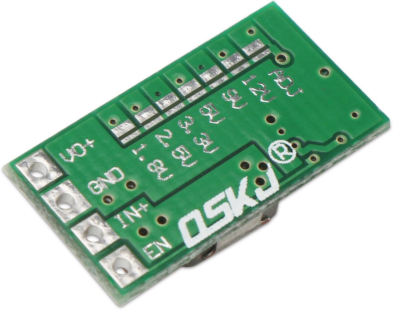
図4:下 view 固定ボリュームのモジュールtage選択パッド。
Procedure for Fixed Voltage選択:
- 電源を切る: Ensure the module is completely disconnected from any power source before proceeding.
- Cut ADJ Trace: Locate the 'ADJ' pad on the backside of the module (top left, as shown in Figure 4). Carefully cut the trace connecting the 'ADJ' pad to the main circuit. This disables the adjustable function.
- Solder Desired Voltage Pad: Identify the solder pad corresponding to your desired fixed output voltage (e.g., 5V). Solder this pad to its adjacent common pad.
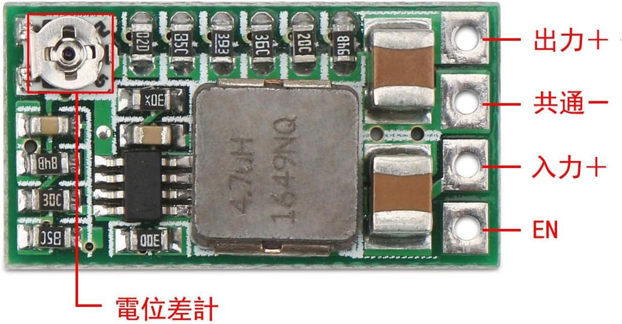
図5:例ample of setting fixed 5V output by cutting the ADJ trace and soldering the 5V pad.

図6:詳細 view of the soldered 5V pad after cutting the ADJ trace.
注記: Some users have reported that the silk screen labels for fixed voltage pads might be offset. Always verify the output voltage with a multimeter after soldering to ensure the correct voltage is achieved. If the initial fixed voltage is not as expected, you may need to adjust the potentiometer slightly after selecting a fixed output, or re-evaluate the soldering points.
4. 操作手順
希望の出力ボリュームに達するとtage is set (either adjustable or fixed), connect your load to the VOUT+ and GND terminals. Ensure that the input voltage is within the specified range (DC 4.5V-24V) and that the output current does not exceed 3A.
- Enable Pin (EN): The integrated enable port is set to operate by default. When the electrical level is low, the module will turn off. This feature can be used for external control of the module's operation.
- 冷却: For output currents approaching the maximum 3A, it is recommended to enhance cooling. This may involve adding a heatsink or ensuring adequate airflow around the module to prevent overheating and maintain stable performance.
5. メンテナンス
The DROK DC-DC Buck Converter Module is designed for reliable operation with minimal maintenance. Follow these guidelines to ensure longevity:
- 清潔に保ちます: Periodically inspect the module for dust or debris accumulation. Clean gently with a soft, dry brush if necessary.
- 湿気を避ける: Protect the module from moisture and corrosive environments.
- 換気: Ensure proper ventilation, especially when operating at higher loads, to dissipate heat effectively.
- 安全な接続: Regularly check all input and output connections to ensure they are secure and free from shorts.
6。 トラブルシューティング
If you encounter issues with your DROK DC-DC Buck Converter Module, consider the following troubleshooting steps:
- 出力なしVoltage:
- 入力ボリュームを確認するtage が存在し、4.5V ~ 24V の範囲内です。
- すべての配線接続の極性が適切であり、接触が安全であることを確認します。
- Ensure the EN pin is not pulled low, which would disable the module.
- 出力ボリュームが正しくありませんtage:
- Adjustable Mode: If using the potentiometer, ensure it is properly adjusted. Turn it slowly and check with a multimeter.
- 固定モード: If fixed voltage is selected, verify that the ADJ trace was correctly cut and the desired voltage pad was properly soldered. Due to potential silk screen offsets, always confirm the output with a multimeter. Re-check soldering if necessary.
- 入力ボリュームを確認するtageは所望の出力volよりも十分に高いtage (at least 1.5V-2V difference for stable buck conversion).
- モジュールの過熱:
- Reduce the output current if it exceeds 1.5A without additional cooling.
- Ensure adequate ventilation around the module. Consider adding a small heatsink for continuous high-current operation.
- 不安定な出力:
- Check for loose connections or intermittent shorts.
- Ensure the load is not exceeding the module's current capacity.
- Verify the input power supply is stable and capable of providing sufficient current.
7. 保証とサポート
保証情報やテクニカルサポートについては、販売店の製品リストを参照してください。 webサイトをご覧いただくか、販売者に直接お問い合わせください。購入証明書として購入レシートを保管してください。


