1.製品オーバーview
The Eaton Cutler-Hammer KT3400T is a 400 Ampere (400A) Series C Thermal-Magnetic Circuit Breaker Trip Unit. This device is designed to provide overcurrent protection in electrical systems by detecting and interrupting fault currents. It features adjustable settings for both instantaneous (Im) and long-time (In) trip functions, allowing for precise protection coordination. The trip unit is an essential component for ensuring the safety and reliability of electrical circuits.

図1: 前面 view of the KT3400T Trip Unit, showing the adjustable dials for current settings and the "Push to Trip" button.
2. セットアップとインストール
Installation of the KT3400T Trip Unit should only be performed by qualified electrical personnel in accordance with all applicable national and local electrical codes and standards. Ensure that the main power supply to the circuit is disconnected and locked out before beginning any installation work.
2.1 取り付け
The trip unit is designed for DIN Rail mounting. Securely attach the unit to the appropriate circuit breaker frame. Ensure all connections are tight and properly torqued to prevent loose connections and potential hazards.
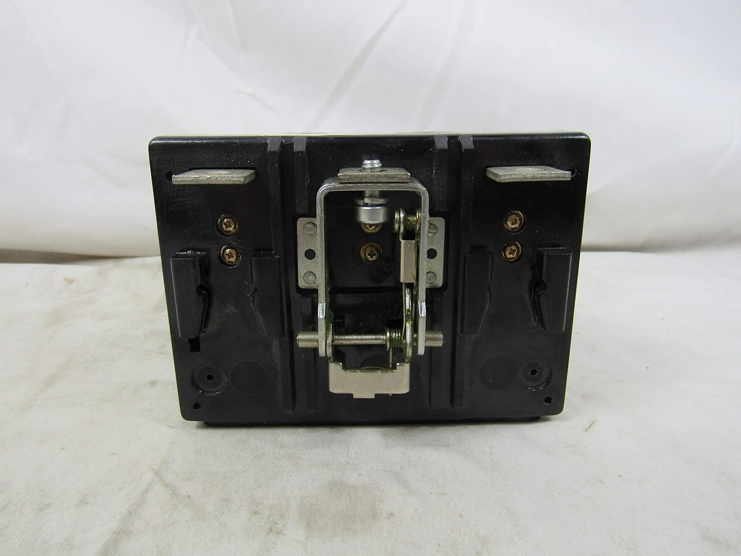
図2:背面 view of the KT3400T, illustrating the mounting points for integration into a circuit breaker frame.

図3:上 view of the KT3400T, showing the integrated mounting hardware for secure attachment.
2.2電気接続
Connect the main power conductors to the appropriate terminals on the trip unit. The unit is rated for 400 Amps. Verify that the conductor size is adequate for the intended current and that all connections are clean and free of debris.

図4:下 view of the KT3400T, displaying the three main terminals for electrical connections.
2.3 付属品の取り付け
For proper installation of accessories such as shunt trip, low energy shunt trip, auxiliary switch, alarm signal lockout, UVR handle reset, UVR manual reset, UVR automatic reset, and UVR electrical reset, refer to the related instruction leaflet. The part numbers for these accessories are typically found on a label on the unit itself or in the accompanying documentation.

図5:側面 view of the KT3400T, showing a label with instructions for proper installation of various accessories and their corresponding part numbers (e.g., LL.29C144 for Shunt Trip).
Additional information regarding accessories can be found by referencing the product's unique identifier: 8620160607095537.
3. 操作手順
The KT3400T trip unit provides adjustable thermal-magnetic protection. Understanding and setting these adjustments correctly is crucial for proper circuit protection.
3.1 現在の設定
- In (Long-Time Current): This dial sets the continuous current rating of the circuit breaker. For the 400A unit, this dial typically adjusts the trip point as a multiple of the nominal current. Ensure this setting matches the circuit's design current.
- Im (Instantaneous Current): This dial sets the instantaneous trip point, which is a multiple of the In setting. This protects against high-level short circuits. Adjust this based on the expected fault current levels and coordination requirements of your system.
3.2 Push to Trip Button
The "Push to Trip" button is a manual test feature. Pressing this button will mechanically trip the circuit breaker, verifying the trip mechanism's functionality. This is a diagnostic tool and should be used periodically as part of a maintenance routine.
4. メンテナンス
Regular maintenance helps ensure the longevity and reliable operation of the KT3400T Trip Unit. Always disconnect power before performing any maintenance.
- 目視検査: 定期的にユニットを点検し、物理的な損傷、変色、接続の緩みなどの兆候がないか確認してください。
- クリーニング: Keep the unit clean and free of dust and debris. Use a dry, lint-free cloth for cleaning. Do not use solvents or abrasive cleaners.
- 機能テスト: Utilize the "Push to Trip" button to periodically verify the mechanical tripping function of the circuit breaker.
- 専門的な検査: For critical applications, consider scheduling periodic inspections and testing by certified electrical technicians.
5。 トラブルシューティング
If the circuit breaker trips unexpectedly or fails to trip when expected, consider the following common issues:
- 頻繁につまずく:
- オーバーロード: The connected load may exceed the trip unit's current setting. Reduce the load or verify the setting.
- 短絡: A short circuit in the protected circuit will cause instantaneous tripping. Identify and clear the fault.
- Incorrect Settings: Verify that the In and Im settings are appropriate for the circuit and load.
- つまずき失敗:
- No Fault: Ensure an actual fault condition exists.
- 機械的な問題: The circuit breaker mechanism may be jammed or faulty. Do not attempt to repair; replace the unit.
- 配線ミス: すべての電気接続が安全かつ正しいことを確認します。
- ユニットの過熱:
- 緩い接続: Check all terminal connections for tightness. Loose connections can cause resistance and heat buildup.
- オーバーロード: Continuous operation near or above the rated current can cause overheating.
For persistent issues, consult a qualified electrician or contact Eaton customer support.
6. 仕様
| 特徴 | 詳細 |
|---|---|
| ブランド | イートン |
| モデル番号 | けーた |
| 現在の評価 | 400 Amps |
| 遮断器のタイプ | Thermal-Magnetic |
| 取り付けタイプ | DINレールマウント |
| 極数 | 3 |
| パッケージ寸法 | 6 x 6 x 4インチ |
| アイテム重量 | 1.85 ポンド |
| 初回利用可能日 | 3年2016月XNUMX日 |
| メーカー | イートン |

図6:側面 view of the KT3400T, showing the product barcode and model number for identification.
7. 保証情報
Warranty terms and conditions for the Eaton Cutler-Hammer KT3400T Circuit Breaker Trip Unit are provided by the manufacturer, Eaton. For detailed warranty information, including coverage period and claims process, please refer to the documentation supplied with your product or visit the official Eaton website. It is recommended to retain your proof of purchase for warranty purposes.
8. カスタマーサポート
For technical assistance, product inquiries, or support regarding the Eaton Cutler-Hammer KT3400T Trip Unit, please contact Eaton customer service. You can typically find contact information, including phone numbers and online support portals, on the official Eaton webサイトまたは製品パッケージ内に記載されています。
イートンの公式ウェブサイトをご覧ください website for the latest product information and support resources: イートン


