1. はじめに
This manual provides essential information for the safe and efficient operation of your AIMS Power 6000 Watt 24 VDC Pure Sine Inverter Charger, Model PICOGLF60W24V240VS. This unit is designed to convert 24VDC battery power into 120/240 VAC split phase pure sine wave electricity, suitable for a wide range of applications including homes, boats, RVs, solar systems, and mobile businesses. It features an 85A smart battery charger and a 40A automatic transfer switch.
Key features include 6000W continuous power, 18000W surge capability for 20 seconds, and compatibility with 8 different battery technologies, including lithium. The inverter also incorporates various protections and advanced features for reliable performance.
2. 安全情報
警告: This product may contain materials cautioned by California Proposition 65. Always handle with care and refer to local regulations.
高音量TAGE警告: Do not open the unit unless qualified to do so. High voltage is present inside. Always read and understand all instructions before working on this product to prevent electric shock or injury.
- Ensure proper ventilation; do not block the vents and fans.
- Use appropriate size and length of wires according to NEC color codes and local electrical standards.
- Always disconnect battery power before performing any maintenance or wiring.
- ユニットが適切に接地されていることを確認してください。
3.製品オーバーview
The AIMS Power PICOGLF60W24V240VS is a robust inverter charger designed for demanding power needs. Below are images highlighting key components and features.
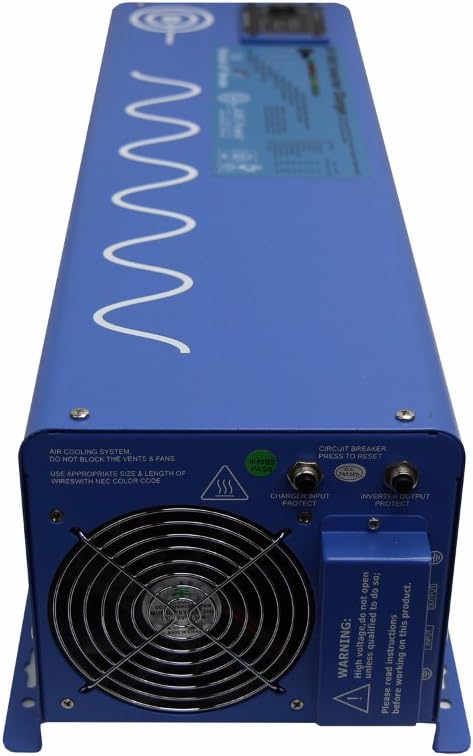
図3.1: フロント view of the AIMS Power 6000 Watt Inverter Charger. Note the warning label regarding high voltage and the need to read instructions.

図3.2: 後方 view of the inverter charger, displaying the positive (red) and negative (black) battery terminal connectors, cooling fan, LCD remote port, LED remote port, and dip switches for configuration.

図3.3: 詳細 view of the rear panel, highlighting the battery terminal connectors, LCD and LED remote ports, Auto Generator Start terminal, Battery Temp Sensor port, and the bank of dip switches (SW1-SW5) for various function settings.

図3.4: 側 view of the inverter charger, showing the AC input and output terminal block. This is where the 120/240 VAC split phase connections are made. Also visible are the circuit breaker and cooling fan.
4. セットアップとインストール
Proper installation is crucial for the safe and efficient operation of your inverter charger. It is recommended that installation be performed by a qualified electrician.
4.1. 取り付け
- Mount the inverter in a dry, well-ventilated area, away from direct sunlight, heat sources, and flammable materials.
- Ensure at least 30cm (12 inches) of clear space around the cooling fan and vents to allow for adequate airflow.
- The unit can be mounted horizontally or vertically, ensuring secure fastening.
4.2。 バッテリー接続
- Connect the 24VDC battery bank to the large positive (red) and negative (black) terminals on the rear of the inverter (refer to Figure 3.2 and 3.3).
- Observe correct polarity: connect positive to positive and negative to negative. Incorrect polarity will cause damage.
- Use appropriate gauge cables for your battery bank and inverter capacity. For a 6000W inverter, heavy gauge cables (e.g., 2/0 AWG or larger) are required to minimize voltag落下を防ぎ、安全を確保します。
- すべての接続がしっかりと固定されていることを確認してください。
4.3. AC Input/Output Connections
- The inverter supports 120/240 VAC split phase output. Connect your AC loads to the AC output terminal block (refer to Figure 3.4).
- For charging, connect a 240 VAC input source (e.g., grid power or generator) to the AC input terminal block.
- If using with a generator transfer switch, use hardwire hookup from this inverter. The inverter is tolerant of grounding the neutral when in inverter mode. This prevents GFCI outlet tripping due to additional neutral-ground connections in the main breaker box.
- Ensure all AC wiring adheres to local electrical codes and standards.
4.4. 接地
- Connect the grounding electrode terminal on the inverter to a reliable earth ground.
4.5. オプションの接続
- Remote Panel: Connect an optional remote panel to the LCD or LED remote port for convenient monitoring and control.
- バッテリー温度センサー: Connect the included battery temperature sensor to the designated port to optimize battery charging based on temperature.
- 自動ジェネレータ起動: Connect compatible auto generator start systems to the dedicated terminal for automatic generator activation when battery voltageは低いです。
ビデオ4.1: このビデオでは、view of the inverter's features and potential setup considerations. (Duration: 2:42)
5. 操作手順
Once installed, the inverter charger offers several operational modes and settings.
5.1.電源のオン/オフ
- Locate the On/Off switch on the unit. Press to power on or off.
- 電源を入れる前に、すべての接続が安全であることを確認してください。
5.2. ディップスイッチの設定
The inverter features a bank of dip switches (SW1-SW5) on the rear panel (refer to Figure 3.3) to configure various operational parameters, such as battery priority, charger settings, and power save mode. Consult the detailed manual for specific switch configurations for your application.
5.3. Charger Operation
- The built-in 85A multi-stage smart charger will automatically charge your battery bank when a 240 VAC input source is connected.
- The charger rate can be adjusted using the charge current control dial.
- The inverter supports 8 different battery charger settings, which can be selected via dip switches.
- The battery temperature sensor helps optimize charging by adjusting parameters based on ambient temperature.
5.4. Transfer Switch Functionality
- The integrated 40A transfer switch automatically switches between inverter power and an external AC source (grid/generator) with a typical transfer time of 10ms.
- This allows for seamless power transition for connected loads.
5.5. Power Save Mode
- The selectable 25W power save mode (hibernation) reduces idle consumption, conserving battery power when no significant load is detected.
6. メンテナンス
定期的なメンテナンスにより、インバーター チャージャーの寿命が長くなり、最適なパフォーマンスが確保されます。
- 換気: Periodically check that the cooling fan and air vents are clear of dust and debris. Blocked vents can lead to overheating and reduced performance.
- 接続: Annually inspect all electrical connections (battery, AC input/output, ground) for tightness and corrosion. Loose connections can cause arcing and damage.
- クリーニング: Keep the exterior of the unit clean and dry. Do not use harsh chemicals or abrasive cleaners.
- 環境: 動作環境が指定された温度と湿度の範囲内であることを確認してください。
7。 トラブルシューティング
This section addresses common issues you might encounter with your inverter charger.
7.1. No AC Output / Inverter Not Turning On
- バッテリー接続を確認してください: Ensure battery cables are securely connected and polarity is correct.
- バッテリー巻tage: Verify that the battery bank voltage is within the operational range (21.0Vdc-32.0Vdc). Low battery voltage will trigger an alarm or trip the unit.
- 遮断器: Press the circuit breaker on the unit to reset it if it has tripped. Note: If the power save feature is ON, you may need to turn it OFF to reset the GFCI outlet breaker.
- オーバーロード: Disconnect some loads and restart the inverter if an overload protection has been activated.
7.2. Charger Not Functioning Correctly
- AC入力: Ensure a stable 240 VAC input source is connected to the AC input terminals.
- 充電器の設定: Verify that the dip switch settings for the battery charger are correct for your battery type.
- Charger Cycling: If the charger constantly cycles (0 amps to 20/40 amps, then cuts off and restarts), ensure the AC input power quality is stable. While the unit is designed to be robust, unstable input power can affect charging behavior.
7.3. GFCI Outlet Tripping
- If the GFCI outlet trips, ensure the power save feature is OFF before attempting to reset the breaker.
- When using the inverter with a generator transfer switch, ensure hardwire connections are used to prevent tripping due to additional neutral-ground connections in the main breaker box.
8. 仕様
Detailed technical specifications for the AIMS Power PICOGLF60W24V240VS Inverter Charger.
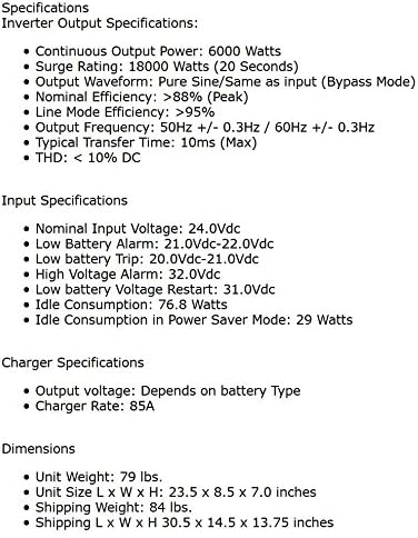
図8.1: Detailed specifications including output, input, charger, and dimensions.
8.1. Inverter Output Specifications
- 連続出力電力: 6000ワット
- サージ定格: 18000 Watts (20 seconds)
- 出力波形: Pure Sine / Same as input (Bypass Mode)
- Nominal Efficiency: >88% (Peak)
- Line Mode Efficiency: >95%
- 出力周波数: 50Hz +/- 0.3Hz / 60Hz +/- 0.3Hz (Auto Detect)
- Typical Transfer Time: 10ミリ秒
- 最低賃金: <10% DC
8.2. DC Input Specifications
- DC Nominal Input Voltage: 24.0Vdc
- 最小開始ボリュームtage: 20.0Vdc
- 低電池アラーム: 21.0Vdc~22.0Vdc
- Low Battery Trip: 20.0Vdc~21.0Vdc
- ハイボリュームtageアラーム: 32.0Vdc
- 低バッテリー容量tage Restart: 26.6Vdc
- アイドル消費量: 46.5W
- Power Saver Mode Idle Consumption: 18.9W
8.3. Charger Specifications
- 出力巻tage: バッテリーの種類によって異なります
- Charger Rate: 85A
8.4.物理的仕様
- 商品の重量: 50ポンド
- 製品寸法(長さ x 幅 x 高さ): 23.5 x 8.59 x 7.05インチ
- モデル名: PICOGLF60W24V240VS
9. 保証
The AIMS Power PICOGLF60W24V240VS Inverter Charger comes with a Manufacturer Warranty. While specific terms may vary, customer feedback indicates a typical one-year warranty period. Please refer to the warranty card included with your product or contact AIMS Power directly for the most current and detailed warranty information.
10. サポート
For technical assistance, warranty claims, or any questions regarding your AIMS Power inverter charger, please contact AIMS Power customer support. All technical and warranty support is provided from their facility in Nevada, USA.
Refer to the official AIMS Power web連絡先の詳細については、サイトまたは製品に付属のドキュメントをご覧ください。


