
1. はじめに
The GODIYMODULES INA333 is a low-power, precision instrumentation amplifier module designed for various electronic sensing and DIY projects. It features low offset voltage, low drift, and low noise, making it suitable for applications requiring high accuracy and stability. This manual provides essential information for the proper setup, operation, and maintenance of your INA333 module.
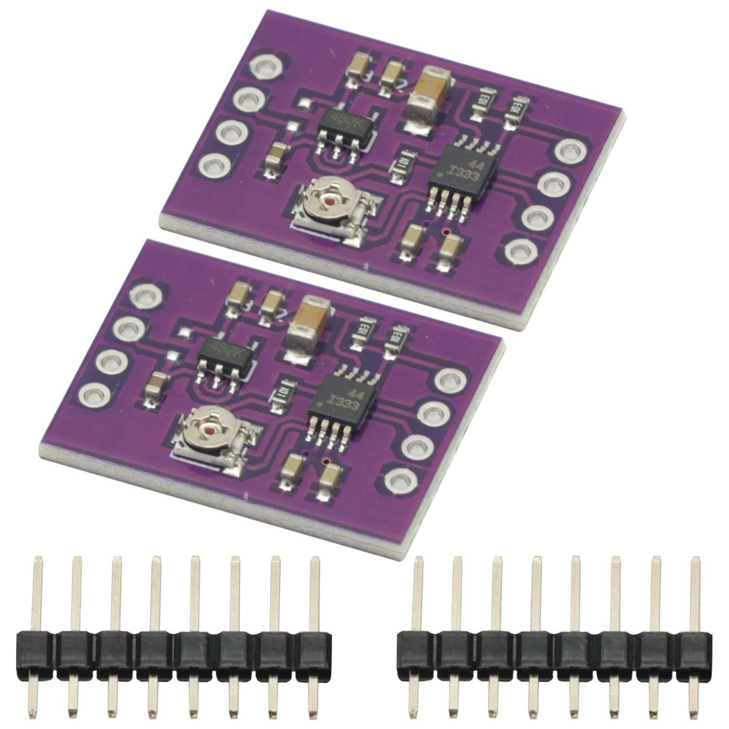
Figure 1: INA333 Low Power Precision Instrumentation Ampliifier モジュール。
2. 主な特徴
- Low-power, precision instrumentation amplifier。
- 低オフセットボリュームtage: 25 µV (Maximum) at G ≥ 100.
- Low Drift: 0.1 µV/°C at G ≥ 100.
- Low Noise: 50 nV/√Hz at G ≥ 100.
- Wide Supply Range: +1.8V to +5.5V.
- Integrated 3 operational ampリファイアの設計。
3. 箱の中身
パッケージには以下のアイテムが含まれている必要があります:
- 2 x INA333 Low Power Precision Instrumentation Ampliifier モジュール。
- Associated pin headers for connection.

Figure 2: Two INA333 modules and pin headers included in the package.
4. 技術仕様
| パラメータ | 価値 |
|---|---|
| モデル | Mod-INA333-002 |
| ブランド | GODIYモジュール |
| Ampリファイアタイプ | 計装 Ampリファイアー |
| チャンネル数 | 3 (Operational Amplifiers) |
| 最小供給量tage | 1.8 ボルト (DC) |
| 最大供給量tage | 5.5 ボルト (DC) |
| 低オフセットボリュームtage | 25 µV (Max, G ≥ 100) |
| Low Drift | 0.1 µV/°C (G ≥ 100) |
| 低ノイズ | 50 nV/√Hz (G ≥ 100) |
5. セットアップとインストール
This section details the steps for connecting and setting up your INA333 module. Ensure all power is disconnected before making any connections.
5.1 ピン配置図
The INA333 module features several pins for power, input, output, and reference voltage. Refer to the pinout diagram below for proper identification.

Figure 3: Pinout of the INA333 module. Key pins include VREF, VOUT, 3.3V, GND, VCC, VIN-, and VIN+.
- VCCC: いいえ Power supply input (+1.8V to +5.5V).
- GND: アース接続。
- VIN+: Non-inverting input for the differential signal.
- VIN-: Inverting input for the differential signal.
- VOUT: Amp固定出力ボリュームtage.
- 参照番号: 参考巻tage input for the output. Typically connected to GND for a unipolar output or a specific voltage for bipolar output.
- 3.3V: Onboard 3.3V regulator output (if applicable, check schematic for details).
5.2 基本接続図
The following schematic illustrates a typical connection for the INA333 module. This diagram provides a general guide for integrating the module into your circuit.

Figure 4: Basic schematic diagram for the INA333 module, showing power, input, and output connections.
For detailed circuit implementation and gain configuration, refer to the full schematic diagram and the INA333 datasheet from Texas Instruments.

Figure 5: Detailed circuit diagram of the INA333 module, including the TPS73033DBVT regulator and INA333 IC connections.
6. 操作
The INA333 module is designed to amplify small differential signals with high precision. Its operation primarily involves providing power, input signals, and setting the gain.
6.1 電源
Connect a stable DC power supply within the range of +1.8V to +5.5V to the VCCC の そして グランド pins. Ensure the power supply is clean and free from excessive noise to maintain the amplifier's precision.
6.2 Input Signal Connection
Connect your differential input signal to the VIN + そして ヴィン- pins. The INA333 is optimized for measuring small voltage differences between these two points, rejecting common-mode noise.
6.3出力Voltage
の amplified output signal is available at the VOUT pin. The output voltage range will depend on the supply voltageと基準体積tage (VREF).
6.4 ゲイン調整
The gain of the INA333 is set by an external resistor, typically labeled RG. The module includes a potentiometer (visible in Figure 6) which allows for adjustable gain. Rotate the potentiometer using a small screwdriver to adjust the amplification factor according to your application's requirements. Refer to the INA333 datasheet for the precise gain formula and resistor values.

図6:上 view of a single INA333 module, highlighting the potentiometer used for gain adjustment.
7. メンテナンス
The INA333 module is a robust electronic component designed for long-term operation with minimal maintenance. Follow these guidelines to ensure its longevity:
- 清潔に保ちます: Avoid dust, dirt, and moisture accumulation on the module. Use a soft, dry brush or compressed air for cleaning if necessary.
- 取り扱いにはご注意ください: Electronic components are sensitive to electrostatic discharge (ESD). Handle the module by its edges and use appropriate ESD precautions.
- 適切な保管: モジュールは、直射日光や極端な温度を避け、乾燥した涼しい環境に保管してください。
- 過剰を避けるtage: 供給量を確認するtage and input signals do not exceed the specified maximum ratings to prevent damage.
8。 トラブルシューティング
If you encounter issues with your INA333 module, consider the following troubleshooting steps:
- No Output/Incorrect Output:
- Verify power supply connections (VCC and GND) and ensure the voltage is within the +1.8V to +5.5V range.
- Check input signal connections (VIN+ and VIN-) for proper polarity and continuity.
- Ensure the VREF pin is correctly connected (e.g., to GND for unipolar output).
- Adjust the gain potentiometer to see if the output changes.
- Excessive Noise in Output:
- Ensure your power supply is stable and filtered.
- Check for proper grounding of the module and your sensor.
- Keep input signal wires short and shielded if possible.
- Verify that the operating environment is free from strong electromagnetic interference.
- モジュールの電源が入らない:
- Double-check all power connections.
- 体積を測定するtage at the VCC pin to confirm it is receiving power.
- Inspect the module for any visible damage or short circuits.
これらの手順を実行しても問題が解決しない場合は、カスタマー サポートに問い合わせて、さらにサポートを受けてください。
9. サポートと保証
For technical support, product inquiries, or warranty information, please refer to the seller's contact details on the platform where you purchased this product. Keep your purchase receipt or order number handy for faster service.
GODIYMODULES is committed to providing quality electronic components. While specific warranty terms may vary by region and retailer, we strive to ensure customer satisfaction. Please reach out to your point of purchase for detailed warranty policies.