
導入
This manual provides detailed instructions for the setup, operation, and maintenance of your diymore ESP32 Display Development Board. This board integrates an ESP32 module with a 2.8-inch LCD touch display, offering WiFi, Bluetooth, and extensive IoT connectivity for various development projects.
製品終了view
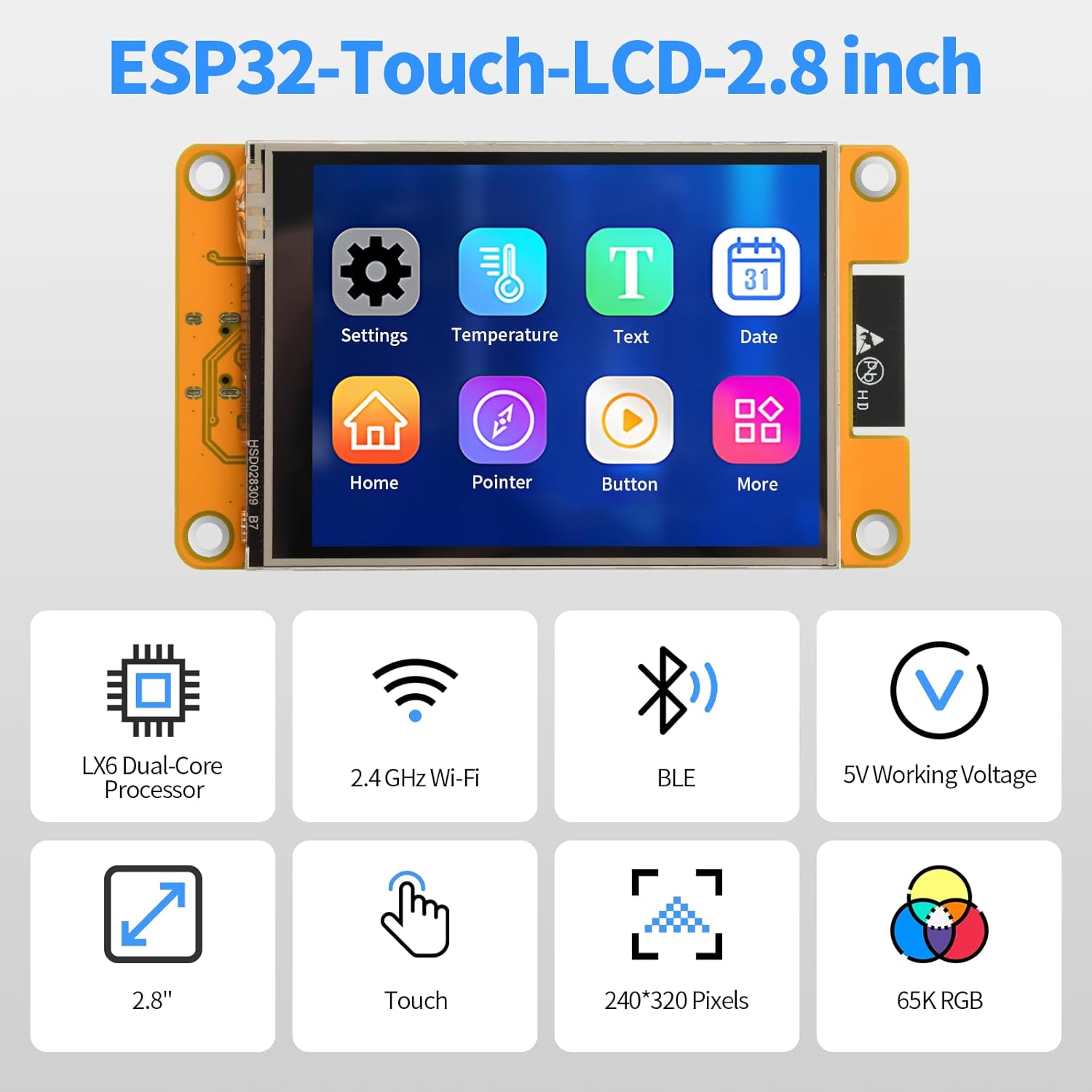
The diymore ESP32 Display Development Board is a versatile module designed for embedded systems and IoT applications. It features a 2.8-inch color LCD with a resolution of 240x320 pixels and touch functionality. The board includes a TYPE-C connector for easy programming and power supply, a Micro-TF card slot for memory expansion, and support for external speakers and lithium batteries.
主な特徴:
- Integrated ESP32 module with WiFi and Bluetooth (BLE) connectivity.
- 2.8-inch 240x320 pixel color LCD touch display.
- TYPE-C USB port for power and data transfer.
- Micro-TF card slot for expandable storage.
- Support for external speakers and audio playback.
- Three-color RGB indicator for status display.
- External lithium battery support with integrated charging management.
- Multiple interface support: UART, SPI, I2C, PWM, ADC, DAC.
- Built-in flash memory, LwIP, and FreeRTOS.
- Compatibility with various development environments: Arduino IDE, MicroPython, Scratch 3.0, Espressif IDF, PlatformIO.
- Supports LVGL GUI and Human-Machine Interface (HMI) development.
コンポーネントの識別:
Refer to the diagram below for the location and function of key components on the development board.

- ESP32-WROOM-32 module: コア処理装置。
- 2.8インチLCDディスプレイ: The primary visual output and touch input interface.
- マイクロSDカードスロット: For external memory expansion.
- TYPE-C: USB port for power and programming.
- リセットボタン: Resets the ESP32 module.
- BOOT ボタン: ファームウェアをフラッシュするためのブートローダー モードに入るために使用されます。
- Lithium battery interface: Connector for an external 3.7V lithium polymer battery.
- UART serial port: シリアル通信用。
- Horn interface: 外部スピーカーを接続します。
- 色: Three-color LED indicator.
- SPI peripheral interface: For connecting SPI devices.
- Extended pins: General purpose input/output (GPIO) pins for connecting other modules and sensors.
仕様
| パラメータ | 価値 |
|---|---|
| 営業巻tage | 5.0ボルト |
| Backlight Current | 75mA |
| ESP32 Reset Current | 40mA |
| Display Only Operating Current | 130mA |
| Total Operating Current (Display, Speaker, Battery Charge) | 480mA |
| Power Consumption (Display Only) | 0.65ワット |
| Lithium Battery Charging Voltage範囲 | 4.2 - 6.5V |
| Lithium Battery Charging Current (Module Effective) | 290 mA (Max: 500 mA) |
| Recommended External Battery | 3.7 V Lithium Polymer Battery |
| プロセッサ | LX6 Dual-Core |
| 表示サイズ | 2.8インチ |
| ディスプレイ解像度 | 240 x 320 ピクセル |
| 接続性 | 2.4 GHz Wi-Fi, Bluetooth (BLE) |
| アイテム重量 | 90グラム |
| メーカー部品番号 | AM03-FBBA0066-004 |

設定
- 電源: Connect the development board to a 5V power source using the provided TYPE-C USB cable. You can connect it to a computer's USB port or a compatible USB power adapter.
- ドライバーのインストール: Depending on your operating system, you may need to install USB-to-serial drivers (e.g., CP210x or CH340G drivers) for your computer to recognize the ESP32 board. Refer to the ESP32 documentation for specific driver requirements.
- 開発環境のセットアップ:
- Install your preferred Integrated Development Environment (IDE), such as Arduino IDE, PlatformIO, or Espressif IDF.
- Configure the IDE to support ESP32 development boards. This typically involves installing the ESP32 board package.
- For graphical user interface (GUI) development, consider setting up LVGL.
- Initial Program Upload:
- Connect the board to your computer via the TYPE-C USB cable.
- Select the correct board and COM port in your IDE.
- Write or load your program code.
- Compile the code and upload it to the ESP32 board. Ensure the correct board and port are selected.
- If the upload fails, try holding down the BOOT button while pressing and releasing the RESET button, then release BOOT, and attempt the upload again.
- Micro-TF Card (Optional): Insert a Micro-TF card into the designated slot for additional storage if your application requires it.
- 外部スピーカー(オプション): Connect an external speaker to the Horn interface if audio output is needed.
- External Battery (Optional): For portable applications, connect a 3.7V lithium polymer battery to the lithium battery interface. The board includes a charging management circuit.

操作手順
- 基本操作: Once powered, the display will activate according to the loaded firmware. If no program is loaded, it may show a default boot screen or remain blank.
- タッチスクリーン操作: Use the included stylus or your finger to interact with the touch display. The responsiveness and functionality depend on the application programmed onto the ESP32.
- Programming and Firmware Upload:
- Connect the board to your computer via the TYPE-C USB port.
- Open your chosen IDE (e.g., Arduino IDE).
- Write or load your program code.
- Compile the code and upload it to the ESP32 board. Ensure the correct board and port are selected.
- If the upload fails, try holding down the BOOT button while pressing and releasing the RESET button, then release BOOT, and attempt the upload again.
- IoT Applications:
- Utilize the integrated WiFi and Bluetooth for remote monitoring, control, and data exchange.
- Develop applications for remote data query, environmental monitoring, and parameter adjustment via mobile apps or web インターフェースの頂点を体現しています。
- オーディオ再生: If an external speaker is connected, the ESP32 can be programmed to play audio files or generate sounds.
- RGBインジケーター: Observe the three-color RGB LED for status indications as defined by your custom firmware.


メンテナンス
- クリーニング: Keep the board and display clean. Use a soft, dry cloth to wipe the screen. Avoid abrasive cleaners or solvents.
- ストレージ: Store the development board in a dry, anti-static environment when not in use. Avoid extreme temperatures and humidity.
- 取り扱い: Handle the board by its edges to avoid touching sensitive electronic components. Static electricity can damage the board.
- ファームウェアの更新: Regularly check for updated firmware or library versions for the ESP32 and display drivers to ensure optimal performance and access to new features.
- バッテリーのケア (該当する場合): If using an external lithium battery, follow standard battery safety guidelines. Do not overcharge or deep discharge the battery.
トラブルシューティング
- Problem: Board not recognized by computer.
- 解決: Ensure USB-to-serial drivers are correctly installed. Try a different USB cable or port. Verify the cable is a data cable, not just a charging cable.
- Problem: Firmware upload fails.
- 解決:
- Check if the correct board and COM port are selected in your IDE.
- Try holding the BOOT button, then pressing and releasing リセットしてから解放asing BOOT before initiating the upload.
- 他のアプリケーションがシリアル ポートを使用していないことを確認します。
- コードがエラーなしでコンパイルされることを確認します。
- Problem: Display is blank or shows garbled output.
- 解決:
- Confirm the display is properly connected to the board (if detachable).
- Check your code for correct display initialization and drawing commands.
- 電源が安定していて十分であることを確認してください。
- Problem: Touch screen is unresponsive or inaccurate.
- 解決:
- Calibrate the touch screen if your firmware supports it.
- Ensure the touch screen drivers are correctly implemented in your code.
- Clean the display surface for any obstructions.
- Problem: WiFi or Bluetooth connectivity issues.
- 解決:
- Verify your network credentials (SSID, password) are correct in your code.
- Ensure the antenna (if external) is properly connected.
- Check for interference from other 2.4 GHz devices.
- Update ESP32 core libraries in your IDE.
保証とサポート
For warranty information and technical support, please refer to the official diymore webご購入いただいたレシートは、保証請求の際に購入証明としてお渡しいたしますので、保管してください。
Online resources and community forums for ESP32 development are also available for additional assistance and project ideas.