1. はじめに
The GODIYMODULES SMC05 is an integrated stepper and servo motor driver controller designed for precise control of motor rotation, speed, and angle. Featuring a 1.8-inch color screen and intuitive knob operation, this module supports a wide range of applications requiring accurate motor positioning and speed regulation. It offers multiple control modes and communication options for versatile integration into various systems.
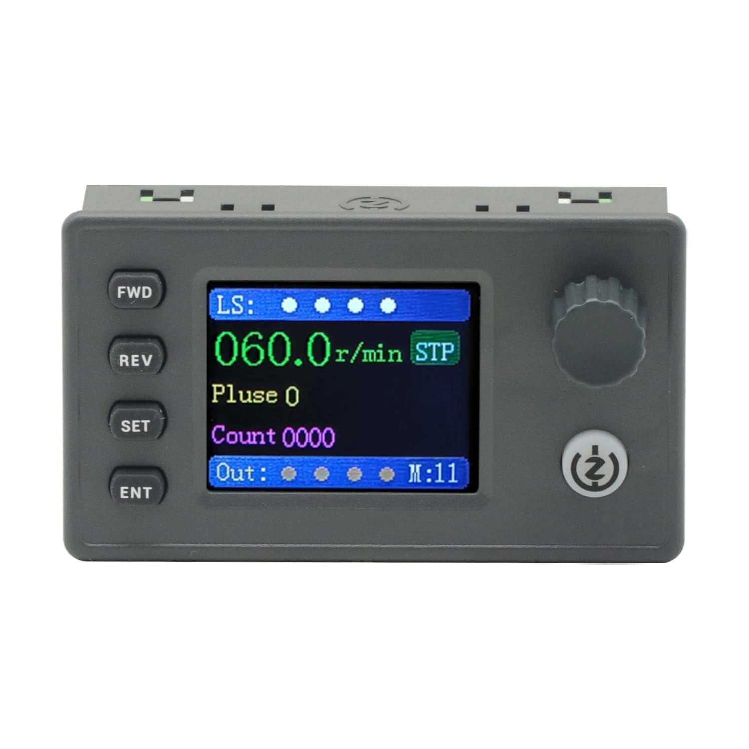
Figure 1: The SMC05 Stepper/Servo Motor Driver Controller, highlighting its 1.8-inch color screen, knob operation, and shortcut buttons.
2 製品の特徴
- 統合制御: Combines stepper motor driver and servo motor control functionalities.
- ワイドVoltage範囲: Operates with a working voltag12~24V。
- コンパクトなデザイン: Product dimensions are 83x48x35.5mm.
- 出力信号: Features 4 output channels with 0V output voltage.
- 入力信号: Includes 4 limit inputs and 3 extended key interfaces.
- High Pulse Frequency: Supports motor pulse frequencies from 1Hz to 200,000Hz.
- カラーディスプレイ: Equipped with a 1.8-inch color screen for clear information display.
- パルスボリュームtage: Motor pulse voltage is 0V output, collector output form.
- コミュニケーション: Supports Modbus protocol via serial port/485.
- 複数のモード: Supports 20 different motion control modes.
- 言語サポート: Display in both Chinese and English.

Figure 2: Key features of the SMC05 controller, including support for various modes and input/output capabilities.
3. セットアップとインストール
3.1 Power Supply and Connections
作業ボリュームを確認しますtage is within the specified range of 12-24V DC. Connect the power supply to the designated terminals. The controller features various input and output interfaces for connecting limit switches, expansion buttons, and motor drives.

図3:詳細 view of the SMC05 controller's extension interface, indicating connections for power, limit switches, expansion buttons, communication, and motor outputs.
3.2 モーターの配線
Proper wiring of the stepper or servo motor drive is crucial for correct operation. Refer to the wiring diagrams provided to ensure all connections are secure and correctly aligned with the motor and power source.

図4:例ample wiring diagram for connecting the SMC05 controller to a microstep driver and a stepper motor.
4. 操作手順
The SMC05 controller features a user-friendly interface with a 1.8-inch color screen, a rotary knob, and several control buttons for easy operation and parameter adjustment.
4.1コントロールパネルオーバーview

Figure 5: Front panel layout of the SMC05 controller with labels for all buttons, the rotary knob, and display indicators.
- FWD Button: 前方回転を開始します。
- REVボタン: 逆回転を開始します。
- SETボタン: Enters the settings menu or exits current settings.
- ENTボタン: 選択を確定するか、サブメニューに入ります。
- ロータリーノブ: Adjusts parameters such as speed, pulse count, and navigates menus.
- 開始/停止ボタン: Starts or stops motor operation.
- 表示画面: Shows current speed, pulse count, motion mode, and various indicators.
4.2 基本操作
- 電源オン: Connect the 12-24V DC power supply. The screen will light up.
- パラメータの設定: を押す セット button to enter the settings menu. Use the rotary knob to navigate through options like アクション, モーター、 そして システム。 プレス 耳鼻咽喉科 選択します。
- Adjusting Speed/Pulse: 内で アクション or モーター settings, you can adjust parameters such as forward pulse, forward speed, reverse pulse, and reverse speed using the rotary knob.
- Starting Motor: パラメータを設定したら、 開始/停止 button to begin motor operation. The motor will rotate according to the configured speed and direction.
- 方向転換: 使用 前向き そして 反逆 buttons to change the motor's rotation direction during operation.
- Stopping Motor: を押す 開始/停止 button again to halt motor movement.
4.3 Advanced Features Demonstration
The following video demonstrates various operational aspects and advanced features of the SMC05 controller, including interface navigation, stepper motor control, use of expansion buttons, limit switches, and output control, as well as servo motor drive integration.
Video 1: Demonstration of the SMC05 controller's interface, stepper motor drive, expansion button functionality, limit switch activation, output control, and servo motor drive operation.
5. 仕様
| 特徴 | 仕様 |
|---|---|
| 製品寸法 | 3.27 x 1.89 x 1.4 インチ (83x48x35.5mm) |
| アイテム重量 | 3.27オンス |
| ワーキングVoltage | 12-24V DC |
| 出力信号 | 4 channels, 0V output voltage |
| 入力信号 | 4 limit inputs, 3 extended key interfaces |
| モーターパルス周波数 | 1Hz - 200,000Hz |
| 表示タイプ | 1.8インチカラースクリーン |
| モーターパルスボリュームtage | 0V output, collector output form |
| 通信プロトコル | Modbus (serial port/485) |
| 含まれるコンポーネント | 1PCS SMC05 Controller |
6. メンテナンス
To ensure the longevity and optimal performance of your SMC05 controller, follow these maintenance guidelines:
- デバイスを清潔に保ち、ほこりやゴミを取り除いてください。清掃には柔らかく乾いた布を使用してください。
- コントローラーを極端な温度、湿度、直射日光にさらさないでください。
- Ensure all connections are secure and free from corrosion. Periodically check wiring for any signs of wear or damage.
- cを開こうとしないでくださいasing or modify the internal components, as this may void the warranty and cause damage.
7。 トラブルシューティング
If you encounter issues with your SMC05 controller, refer to the following common troubleshooting steps:
- 電源なし: 電源の接続を確認し、正しい電圧が供給されていることを確認してください。tage (12-24V DC). Verify the power adapter is functioning.
- モーターが動かない:
- Ensure the motor is correctly wired to the driver and the driver to the controller.
- Check if the motor parameters (speed, pulse) are set correctly on the controller.
- Verify that the Start/Stop button has been pressed to initiate movement.
- Check for any active limit switch inputs that might be preventing movement.
- Incorrect Speed/Direction: Review the speed and direction settings in the controller's menu. Ensure the FWD/REV buttons are used appropriately.
- 表示の問題: If the screen is blank or shows errors, try restarting the device. If the problem persists, contact support.
- Communication Errors (Modbus): Verify the serial port/485 connections and ensure the communication parameters (baud rate, parity, etc.) are correctly configured on both the controller and the connected device.
For persistent issues not resolved by these steps, please contact GODIYMODULES customer support.
8. 保証とサポート
Information regarding specific warranty terms for the GODIYMODULES SMC05 controller is not available in the provided product data. Please refer to the product packaging or the manufacturer's official web詳細な保証情報については、サイトをご覧ください。
For technical support, troubleshooting assistance, or inquiries about the product, please contact GODIYMODULES customer service through their official channels.