
MICTUNING P4-N-4
MICTUNING P4-NEON 4 Gang Switch Panel Instruction Manual
Model: P4-N-4 | Brand: MICTUNING
導入
This manual provides comprehensive instructions for the installation, operation, and maintenance of your MICTUNING P4-NEON 4 Gang Switch Panel. Please read this manual thoroughly before use to ensure proper functionality and safety.

Figure 1: MICTUNING P4-NEON 4 Gang Switch Panel and included components.
パッケージ内容
パッケージにすべてのアイテムが揃っていることを確認します。

Figure 2: All components included in the MICTUNING P4-NEON 4 Gang Switch Panel package.
- パワーハブ
- スイッチパネル
- ワイヤーハーネス
- ACC Wire
- 取り付けブラケット
- 140pcs Switch Labels
- ヒューズタップ
- Wires (Power and Ground)
- ユーザーマニュアル
- ジップタイ
- ファスナー
- MICTUNING Stickers
- 梱包箱
- スペアヒューズ
- サーキットブレーカー (60A)
セットアップとインストール
The MICTUNING P4-NEON switch panel is designed for flexible installation and simplified wiring. The power hub centralizes connections, reducing cable clutter and enhancing safety.
1. Power Hub Installation
Install the power hub in a secure, dry location, typically under the hood, ensuring it is protected from direct elements. Connect the main power and ground wires from the vehicle's battery to the power hub. The included 60A circuit breaker should be installed inline with the main power connection for protection.

図3:例ample of a clean and safe wiring setup using the power hub.

Figure 4: Wiring diagram for the power hub, showing connections for different circuits.
2. スイッチパネルの取り付け
The slim design of the switch panel allows for versatile mounting options. It can be installed horizontally or vertically on surfaces such as the dashboard, A-pillar, or overhead console using the provided mounting brackets and fasteners.

Figure 5: Flexible mounting options for the switch panel, including vertical and horizontal orientations.

Figure 6: The compact design allows for installation in diverse vehicle interior spaces.
3. Connecting the Switch Panel
Connect the switch panel to the power hub using the provided wire harness. Ensure all connections are secure. Apply the appropriate switch labels to the silicone buttons for easy identification of controlled accessories.
操作手順
The P4-NEON switch panel features color-coded backlit silicone buttons for intuitive operation and four distinct control modes.
1. Turning On/Off the Switch Panel
Press any button to turn on the switch panel. The buttons will illuminate according to their current mode. To turn off the backlight, press and hold the power button (rightmost button) for a few seconds. Press any button again to turn the backlight back on.

Figure 7: Turning the backlight off for night driving by pressing the power button.
2. Understanding Control Modes
Each button's backlight color indicates its control mode:
- 赤: Toggle Mode (On/Off)
- 青: Momentary Mode (Active while pressed)
- 紫: Flash Mode (Flashes continuously)
- 緑: Strobe Mode (Strobes continuously)
- 白: Standby Mode (Backlight off, but ready for activation)

Figure 8: The four distinct control modes indicated by button color.
3. Setting Control Modes
To change a button's control mode:
- Press any button to turn on the switch panel.
- Press and hold the "M" (Mode) button. When the red backlight flashes, the panel is in Control Mode Setting state.
- Select the desired switch button you wish to configure. Each press will cycle through the four control modes (Toggle, Momentary, Flash, Strobe), indicated by the button's backlight color.
- Once the desired mode is set, press the "M" (Mode) button again to save the settings and exit the Control Mode Setting state.
Video 1: Detailed instructions on how to set the control modes for each switch button on the MICTUNING P4-NEON panel.
4. 工場出荷時の設定に戻す
To restore the switch panel to its factory default settings:
- Press any button to turn on the switch panel.
- Press and hold the "M" (Mode) button for 7 seconds.
- The backlight will turn off, indicating that the factory settings have been restored.
5. Switching Power Source (Battery/ACC)
The power source for the switch panel can be configured between direct battery power and ACC (Accessory) power. This setting is controlled via a switch on the power hub.
- When the power indicator on the power hub is on, the system is powered directly by the バッテリー.
- When the power indicator on the power hub is オフ, the system is powered by オーストラリア中央委員会 (Accessory) power, meaning it will turn on/off with the vehicle's ignition.
Adjust the switch on the power hub according to your preferred power source. Refer to the markings on the power hub for the correct switch position.
メンテナンス
The MICTUNING P4-NEON switch panel is built with durable materials and features an IP65 waterproof rating, ensuring reliable performance in various conditions.
- クリーニング: 柔らかくてamp cloth to clean the switch panel and power hub. Avoid abrasive cleaners or solvents.
- 検査: Periodically check all wiring connections for tightness and signs of wear or corrosion. Ensure the circuit breaker is functioning correctly.
- ヒューズ: The power hub includes various fuses for each circuit. If a connected accessory stops working, check the corresponding fuse on the power hub and replace it with a spare fuse of the same rating if necessary.
ビデオ2: 終了view of the MICTUNING P4-NEON 4 Gang Switch Panel, highlighting its features and durable construction.
トラブルシューティング
If you encounter issues with your MICTUNING P4-NEON switch panel, refer to the following common troubleshooting steps:
- パネルの電源が入らない:
- Check the main power connection to the vehicle battery.
- Verify the 60A circuit breaker is not tripped.
- Ensure the power source switch on the power hub is correctly set (Battery or ACC).
- アクセサリが動作しない:
- Check the specific fuse for that circuit on the power hub and replace if blown.
- Verify the wiring connection from the power hub to the accessory.
- Ensure the switch button is set to the correct control mode for the accessory.
- バックライトの問題:
- If the backlight is off, press any button to reactivate it.
- If specific buttons are not lighting up, check for loose connections or internal damage.
For further assistance, please contact MICTUNING customer support.
仕様
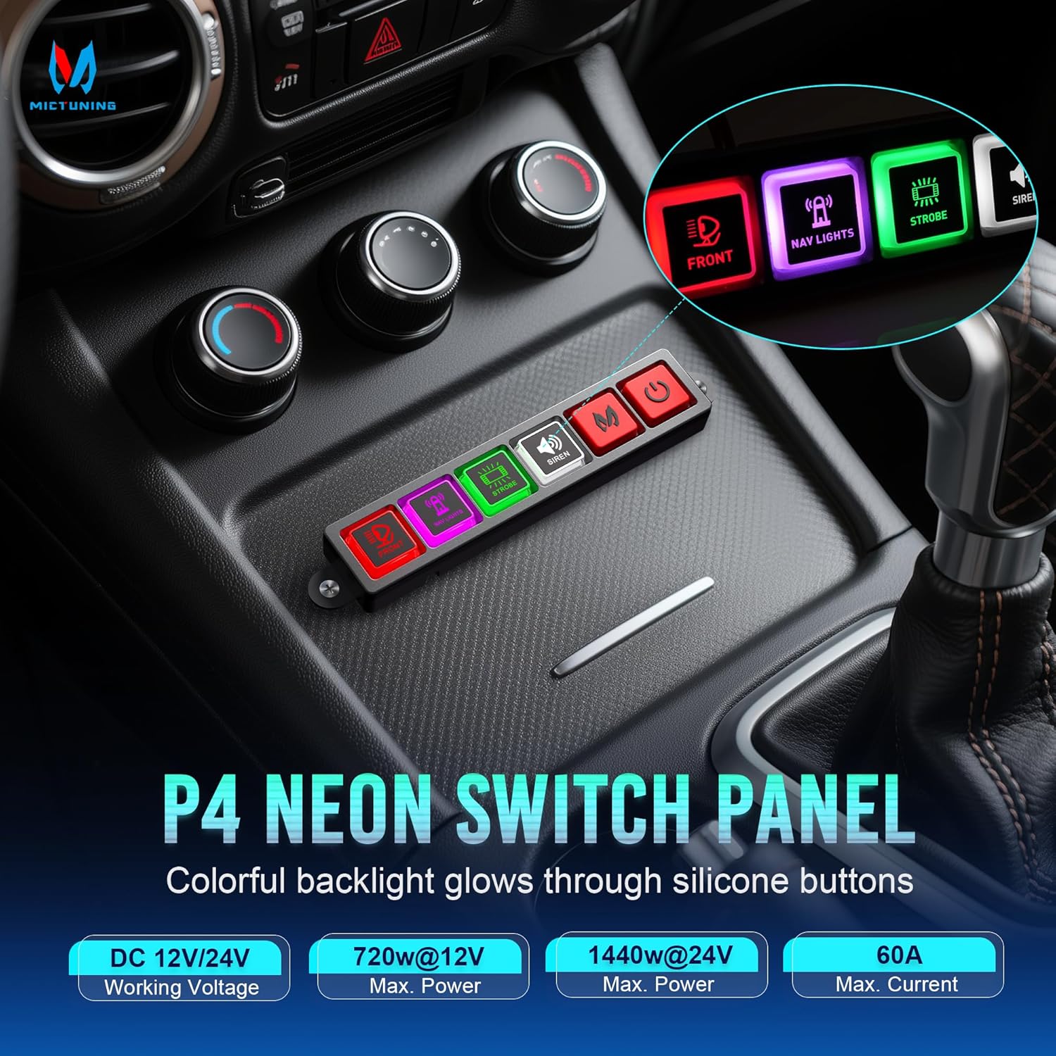
Figure 9: Key technical specifications of the P4-NEON switch panel.
| 特徴 | 詳細 |
|---|---|
| モデル番号 | P4-N-4 |
| 営業巻tage | 12V/24V DC |
| 最大出力 | 720W @ 12V / 1440W @ 24V |
| 最大電流 | 60 Amps |
| 動作温度 | -40°C ~ 105°C |
| 防水等級 | IP65 |
| 回路タイプ | 4ウェイ |
| 製品寸法(長さ x 幅 x 高さ) | 2.68 x 1.77 x 3.74インチ |
| 操作モード | オンオフ |
保証とカスタマーサポート
MICTUNING is committed to providing high-quality products and excellent customer service. Your P4-NEON switch panel comes with lifetime customer support.
If you require assistance or have any questions, please contact MICTUNING customer support. You can typically reach support within 4 hours for friendly assistance.
Amazon経由で販売者に連絡するには:
- Amazonアカウントにログインします。
- 「ご注文」へお進みください。
- Find the order ID for your MICTUNING P4-NEON switch panel.
- Click "Problem with the order".
- Choose "Other issue".
- 「販売者に連絡」をクリックします。
関連文書 - P4-N-4
 |
MICTUNING P8Y RGB 6/8 Gang Switch Panel User Manual User manual for the MICTUNING P8Y RGB 6/8 Gang Switch Panel, featuring wireless app and remote control, IP67 waterproof design, and a relay system. |
 |
MICTUNING P1s APP コントロールスイッチパネル ユーザーマニュアル MICTUNING P1s APPコントロールスイッチパネルの詳細なユーザーマニュアルです。スイッチパネルとコントロールボックスの取り付けガイド、8ギャングおよび12ギャング構成の包括的な配線図、ヒューズブロックの仕様、制御モード設定(定常、モーメンタリー、ストロボ)、Bluetoothアプリとの連携、バックライトのカスタマイズ、よくある質問などを網羅しています。自動車アクセサリーの取り付けに必須のガイドです。 |
 |
MICTUNING P1s RGB Switch Panel User Manual & Installation Guide Comprehensive user manual and installation guide for the MICTUNING P1s RGB Switch Panel. Features include RGB lighting, 6-level brightness, multiple control modes, and app connectivity. Covers packing list, wiring diagrams, installation steps, and troubleshooting. |
 |
MICTUNING P1s-W Wireless RGB Switch Panel User Manual Comprehensive user manual for the MICTUNING P1s-W Wireless RGB Switch Panel. Covers installation, wiring, pairing, control modes, troubleshooting, and specifications for automotive LED lighting and accessory control. |
 |
MICTUNING Q1 RGB ロックライト FAQ MICTUNING Q1 RGB ロック ライトに関するよくある質問と回答。アプリの接続、Bluetooth 信号、色の制御、点滅ライト、電源状態などについて説明します。 |
 |
MICTUNING P1 RGB 12ギャングスイッチパネル ユーザーガイド MICTUNING P1 RGB 12 ギャング スイッチ パネルの包括的なガイド。インストール、配線、照明モード、トラブルシューティングなどを網羅しています。 |
Ask a question about this manual
Ask about setup, troubleshooting, compatibility, parts, safety, or missing instructions. Manuals+ will review the question and use this page’s manual context to help answer it.