
1. はじめに
This manual provides essential information for the setup, operation, and maintenance of your diymore ESP32-S3 DevKitC-1 N16R8 development module. This module is designed for various IoT applications, featuring a high-performance dual-core processor, integrated Wi-Fi, and Bluetooth 5.0 connectivity. Please read these instructions carefully before use to ensure proper functionality and to maximize the module's potential.
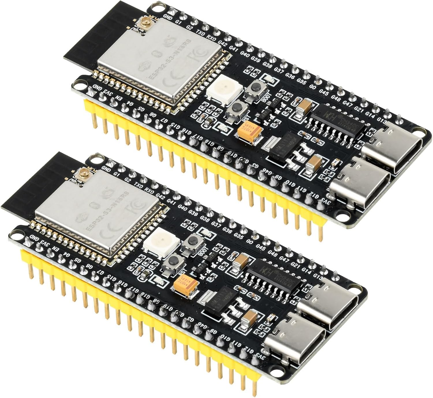
2.製品オーバーview
2.1 主な特徴
- High-Performance Dual-Core Processor: Integrated Xtensa 32-bit LX7 dual-core processor for powerful computing and low power consumption.
- Dual-Mode Wi-Fi and Bluetooth Support: Supports Wi-Fi 802.11 b/g/n and Bluetooth 5.0 (LE) with Bluetooth Mesh capabilities.
- 強化されたデザイン: Upgraded features and additional external antenna interfaces compared to other ESP32-S3 development boards.
- Comprehensive Wi-Fi Functions: Supports WMM, A-MPDU, A-MSDU, and instant block confirmation for improved multitasking efficiency.
- 大容量のストレージ: Integrates 8MB RAM and 16MB Flash memory for complex application development.
2.2 コンポーネントの識別
詳細は下の図を参照してくださいview of the main components and their locations on the ESP32-S3 DevKitC-1 N16R8 module, along with its pinout configuration.


3. セットアップ
3.1 初期接続
- Connect the ESP32-S3 module to your computer using a USB-C cable. The module features two USB-C ports; one for direct USB and OTG, and another for the serial port chip.
- Ensure that the necessary drivers for the USB to serial port chip (CH343p) are installed on your computer. These drivers are typically available from the chip manufacturer's website or common development board driver packages.
- Verify that the power LED (PWR light) on the module illuminates, indicating successful power supply.
3.2アンテナ構成
The ESP32-S3 module supports both an onboard antenna and an external antenna. By default, the onboard antenna is active with a gain of 2dB.

If you intend to use an external antenna, a soldering modification is required to switch the antenna path. This typically involves desoldering a small component or bridging a solder pad. Consult advanced documentation or community resources for detailed instructions on this modification, as it requires precision soldering skills.
3.3開発環境
To program the ESP32-S3 module, you will need a suitable development environment. Popular options include:
- Espressif IoT Development Framework (ESP-IDF): The official development framework for Espressif chips, offering comprehensive tools and libraries.
- Arduino IDE: A user-friendly environment with extensive community support and libraries for ESP32 boards.
- プラットフォームIO: An open-source ecosystem for IoT development, compatible with various IDEs.
Install the chosen development environment and configure it for ESP32-S3 boards according to the respective documentation.
4. 操作手順
4.1 Flashing Firmware
- Prepare your code in the chosen development environment.
- Connect the ESP32-S3 module to your computer via USB-C.
- Select the correct serial port for the module in your IDE.
- を押し続けます ブート ボタンを押してから、 RSTP ... button. Continue holding the BOOT button until the flashing process begins. This puts the module into download mode.
- Initiate the upload/flash process from your development environment.
- Once flashing is complete, release the BOOT button and press the RST button to restart the module and run the new firmware.
4.2 Wi-Fi and Bluetooth Usage
The ESP32-S3 module supports Wi-Fi and Bluetooth 5.0 (LE). These functionalities are controlled programmatically through your firmware. Refer to the ESP-IDF or Arduino libraries for specific functions and examples related to Wi-Fi connectivity, Bluetooth communication, and Bluetooth Mesh networking.
- Wi-Fi: Use standard Wi-Fi libraries to connect to access points, create soft APs, or implement Wi-Fi Direct.
- ブルートゥース: Utilize Bluetooth Low Energy (BLE) libraries for device communication, advertising, and scanning.
5. メンテナンス
The diymore ESP32-S3 module is a robust electronic component, but proper care ensures its longevity and reliable performance.
- ストレージ: 使用していないときは、モジュールを乾燥した静電気防止環境に保管してください。
- 取り扱い: Avoid touching the electronic components directly to prevent electrostatic discharge. Use anti-static precautions.
- クリーニング: If necessary, gently clean the board with a soft, dry brush or compressed air. Do not use liquids or abrasive materials.
- 電源: Ensure a stable 5V power supply when operating the module. Over-voltagコンポーネントが損傷する可能性があります。
6。 トラブルシューティング
6.1 一般的な問題と解決策
- Module not recognized by computer:
- Ensure USB-C cable is fully inserted and functional.
- Verify that the CH343p serial port drivers are correctly installed.
- 別のUSBポートまたはコンピューターを試してください。
- Firmware flashing fails:
- Confirm the module is in download mode (BOOT button held, RST pressed and released).
- Check that the correct serial port is selected in your IDE.
- Ensure your development environment is properly configured for ESP32-S3.
- 電源の安定性を確認します。
- Poor Wi-Fi/Bluetooth signal with external antenna:
- Confirm that the necessary soldering modification has been correctly performed to switch from the onboard antenna to the external antenna connector. Incorrect modification can lead to signal issues.
- Ensure the external antenna is properly connected and functional.
- モジュールの電源が入らない:
- USB-Cケーブルと電源を確認してください。
- Inspect the board for any visible damage or short circuits.
7. 仕様
| 特徴 | 詳細 |
|---|---|
| ブランド | DIYモア |
| モデル名 | ESP32-S3 |
| モデル番号 | 2PCS (referring to the product package quantity) |
| プロセッサ | Xtensa 32-bit LX7 Dual-Core |
| チップセットタイプ | ESP32-S3 |
| RAMメモリサイズ | 8MB |
| Storage Capacity (Flash) | 16MB |
| ワイヤレス接続 | Wi-Fi 802.11 b/g/n, Bluetooth 5.0 (LE) |
| USBポート | 1 (Total, Type-C) |
| 対応デバイス | Smartphone, PC, Camera (general compatibility for development) |

8. 保証とサポート
For warranty information and technical support, please refer to the official diymore website or contact their customer service directly. Product return policies are typically governed by the retailer's terms and conditions, which for this product include a 30-day refund/replacement period. Information regarding spare parts availability and guaranteed software updates is not provided.
You can visit the diymore store for more information: diymore Official Store