
導入
This manual provides detailed instructions for the installation, operation, maintenance, and troubleshooting of your mGYDY 36V 48V 750W KT 25A Electric Bicycle Controller Kit. Please read this manual thoroughly before use to ensure proper function and safety.
パッケージ内容
次のアイテムがパッケージに含まれています。
- 1 x 25A Electric Motor Controller
- 1 x LCD5 Display
- 1 x TT009 Thumb Throttle
- 1 x 1T4 Cable
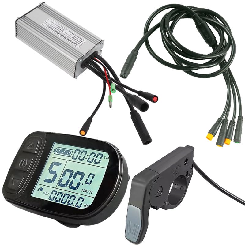
図1:以上view of the mGYDY Electric Bicycle Controller Kit components.
ビデオ1: 開封と終了view of the Electric Bike Brushless Controller Kit components.
仕様
| 特徴 | 説明 |
|---|---|
| アイテムタイプ | コントローラ |
| 材料 | アルミニウム合金、ABS |
| コントローラーボックスサイズ | 約125x66x39mm / 4.9x2.6x1.5インチ |
| コントローラータイプ | ブラシレスモーターコントローラー |
| コネクタタイプ | 防水コネクタ |
| 最大電流 | 25±1A |
| 定格巻tage | DC 36V / 48V |
| 速度設定 | 1-4.2V |
| 定格電流 | 12A |
| ブレーキ入力 | 低レベル |
| 低ボリュームtag保護 | DC 30/40±0.5V |
| 該当するモーター | Usually 750W Motor |
| LCD5 Display Type | GD01 (or S866 as per video) |
| LCD5 Line Length | 225mm (WP Plug) |
| TT009 Throttle Type | Quick Thumb Throttle |
| TT009 Throttle Material | PC+ABS |
| TT009 Throttle Voltage | 12V 24V 36V 48V 52V 60V 72V |
| TT009 Throttle Installation | 右と左 |

Figure 2: Controller dimensions and basic specifications.

Figure 3: LCD5 Display dimensions and specifications.

Figure 4: TT009 Thumb Throttle specifications.
セットアップとインストール
Proper installation is crucial for the safe and efficient operation of your e-bike kit. Ensure all connections are secure and waterproof where applicable.
コントローラー配線手順
Connect the corresponding line interfaces as described below to enable the kit's functions. It is essential to use this kit with a brushless motor and it is only compatible with KT series instrument products.
- Black Long Wire: Connect to the Motor Wire.
- Red and Black Single Big Wire: Connect as the Power Cord.
- Black Long Wire (Fine Hole): Connect to the One for Four/One for Five (9 Cores) cable.
- Black Line and Red Head: Connect to the Light Line.
- Black Wire and Yellow Head: Connect to the Power Assist Sensor Wire.

Figure 5: Controller wiring diagram showing various connections.

Figure 6: 1T4 Cable product connector details.
Display and Throttle Installation
The LCD5 display features an open design for easy installation on 22mm diameter handlebars, eliminating the need to remove the bike handlebars. The 1T4 cable connects the display, thumb throttle, and two brake levers to the controller.

Figure 7: LCD5 Display easy installation feature.
Video 2: Detailed demonstration of controller plug connections, including phase position, display, throttle, Hall sensor, battery, and e-brakes. Also shows display testing and parameter settings.
操作手順
The LCD5 display provides various user parameter setting functions to customize your e-bike's performance.
LCD5 Display Functions
The display shows speed, PAS level, battery level, total mileage, single mileage, light indication, single trip time, and error codes. Refer to the diagram below for button functions and display indicators.

Figure 8: KT-LCD5 e-Bike Display User Manual - Functions and Display.
パラメータ設定
The display allows setting and adjusting motor parameters, speed measurement parameters, speed limit parameters, power parameters, power auxiliary control parameters, minimum controller voltage, and maximum current parameters. To enter parameter setting mode, press and hold the '+' and '-' buttons simultaneously. Use the '+' and '-' buttons to navigate and adjust values. Press the 'M' button to save and exit.
- P01: Backlight brightness (1-3 levels)
- P02: Change metric (0: Km, 1: Mile)
- P03: バッテリーvoltage setting (24V/36V/48V/60V/72V, default 36V). Adjust 36V-60V voltage.
- P04: Hibernate mode time (1-60 minutes, 0: never enter this mode)
- P05: Total assist levels (0-5 levels)
- P06: Wheel size (inch)
- P07: Speed calculation (number of magnets for speed calculation, range: 1-255)
- P08: Speed limit range (0-100km/h)
- P09: Zero speed start (0: zero start, 1: non-zero start)
- P10: 運転モードの選択
- P11: Assist sensitivity
- P12: Assist starting power
- P13: Assist disc type
- P14: Current limit of controller
- P15: 低容量tage protection setting of controller
- P16: ODO distance reset
- P17: Cruise mode selection
- P18: 速度比
- P19: アシストレベル
- P20: プロトコルの選択
メンテナンス
Regular maintenance ensures the longevity and optimal performance of your e-bike kit.
- Keep all components clean and free from dust and debris.
- すべての電気接続部の締め付け具合や摩耗の兆候を定期的に確認してください。
- Ensure waterproof connectors are properly sealed to prevent moisture ingress.
- Inspect cables for any damage or fraying and replace if necessary.
- Store the e-bike in a dry environment when not in use.
トラブルシューティング
If you encounter issues, refer to the error codes displayed on the LCD5 and the following general troubleshooting tips.
Error Codes (from LCD5 Display)
| コード(XNUMX進数) | 説明 |
|---|---|
| E00 | 普通 |
| E01 | 予約済み |
| E02 | ブレーキエラー |
| E03 | Assist Sensor Error |
| E04 | 6KM/H Push Mode |
| E05 | クルーズモード |
| E06 | バッテリー残量が少ないtag保護 |
| E07 | モーターエラー |
| E08 | スロットルエラー |
| E09 | コントローラエラー |
| E10 | COM Receive Error |
| E11 | COM Send Error |
| E12 | BMS通信エラー |
| E13 | Head Light Error |
For any error code, first check all connections. If the issue persists, consult a qualified technician.
保証とサポート
保証情報
この製品には、 1年間のメーカー保証保証請求の際は、購入証明書を保管してください。保証は、通常の使用条件下での製造上の欠陥に適用されます。
カスタマーサポート
For technical assistance, troubleshooting, or warranty inquiries, please contact mGYDY customer support through your retailer or the official mGYDY webサイト。