1.製品オーバーview
The YUHANUS Electric Drop Bolt Lock is designed for use in access control systems, providing enhanced security for various door types. This model operates in NO Mode (Fail-Security), meaning the lock is in a locked state by default when power is off. It will only unlock when power is applied and an authorized signal (e.g., from a push button or remote controller) is received. It features a time delay function for controlled access.
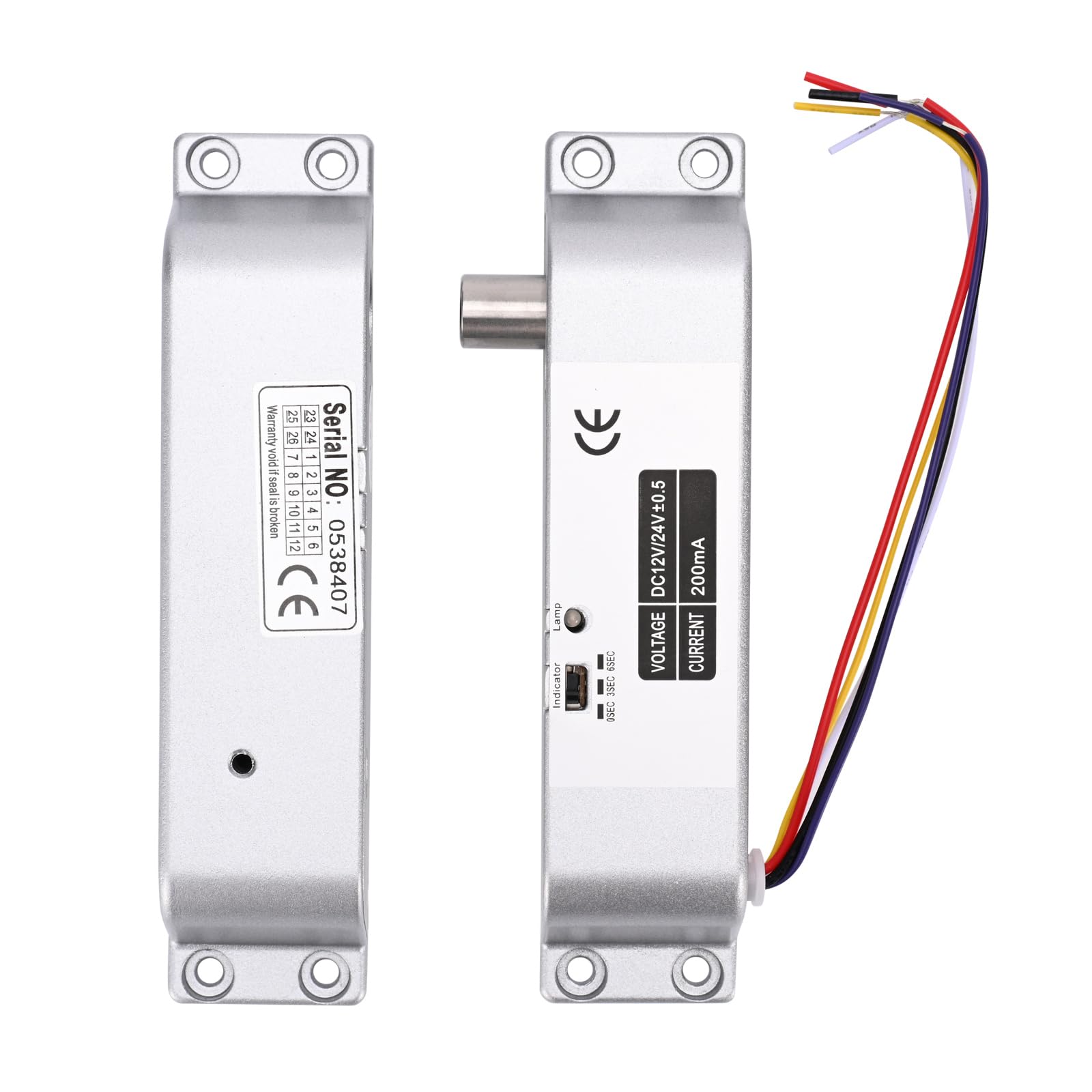
Image 1.1: The YUHANUS Electric Drop Bolt Lock, showcasing its compact design and wiring.
2. 安全情報
- 感電を防ぐため、設置またはメンテナンスを行う前に、すべての電源が切断されていることを確認してください。
- 設置は資格のある人員が行うか、専門家の監督の下で行う必要があります。
- 正しいボリュームを確認するtage (DC 12V) and current specifications before connecting to a power source. Incorrect voltagデバイスが損傷する可能性があります。
- ロックを過度の湿気や極端な温度にさらさないでください。
- 必ず現地の電気規則および規制に従ってください。
3. パッケージ内容
パッケージをチェックして、すべてのアイテムが揃っていることを確認してください。
- Electric Mortise Lock Unit
- パネルカバー
- Induction Lock Component
- Mounting Screws (Set)
- 取扱説明書(本書)
- 適合証明書
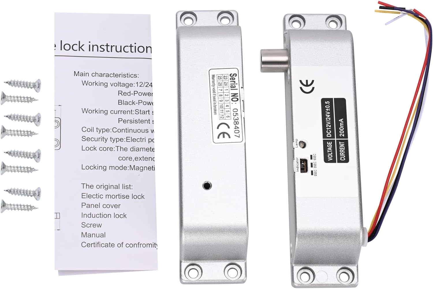
Image 3.1: Contents typically included in the product package, showing the lock units, screws, and a small instruction sheet.
4. 仕様
| 特徴 | 仕様 |
|---|---|
| モデル名 | Electric-Bolt-Lock01-NO |
| 営業巻tage | DC12V |
| 動作電流 | 200mA |
| ロックタイプ | Drop Bolt, Fail-Security (NO Mode) |
| 時間遅延 | 0s / 3s / 6s (Adjustable) |
| 材料 | アルミニウム |
| 寸法(長さ×幅×高さ) | 6 x 1.3 x 1インチ(約150mm x 33mm x 27mm) |
| 取り付けタイプ | 表面実装 |
| 適切なドアの種類 | Wooden door, metal door, fireproof door, etc. |

Image 4.1: Detailed dimensions of the electric drop bolt lock for installation planning.
5. セットアップとインストール
5.1 ロックの取り付け
- ドアとフレームを準備します。 Identify the desired mounting location on the door frame and the corresponding position on the door for the bolt to engage. The lock is surface-mounted.
- 掘削ポイントをマークする: Use the lock unit as a template to mark the screw holes on both the door frame and the door.
- パイロット穴をドリルで開ける: 取り付けネジ用の適切な下穴を開けます。
- ロックを固定する: Attach the main lock unit to the door frame and the induction lock component to the door using the provided screws. Ensure proper alignment for smooth bolt operation.
5.2配線手順
The electric drop bolt lock requires connection to a DC 12V power supply and an access control system. Refer to the wiring diagram below for proper connections.
- 赤いケーブル: 接続する +12V terminal of your power supply control.
- ブラックケーブル: 接続する グランド (Ground) terminal of your power supply control.
- Purple Cable: 接続する いいえ (Normally Open) terminal in your power supply control or access control panel. This connection is crucial for the Fail-Security (NO Mode) operation.
- Other Cables: Yellow and White cables are typically for door status feedback (NC/COM), which may or may not be used depending on your access control system's requirements. Consult your access control system manual for these connections.

Image 5.1: Wiring diagram illustrating connections for the electric bolt lock within a typical access control system, including power supply, keypad, and exit button.
6. 操作手順
6.1 NO Mode (Fail-Security) Operation
This electric drop bolt lock operates in NO Mode (Fail-Security). This means:
- When there is no power, or in case of a power failure, the lock remains in a locked state.
- The lock will only unlock when power is supplied to the lock and an authorized signal is received from the access control system (e.g., pressing a push button, using a remote controller, or entering a code on a keypad).
6.2 Time Delay Function
The lock features an adjustable time delay function, which controls how long the door remains unlocked after an authorized signal is received. The delay can be set to 0 seconds, 3 seconds, or 6 seconds.
To adjust the time delay, locate the small switch or jumper on the side of the lock unit (refer to Image 6.1). Move the switch or adjust the jumpers to select the desired delay setting (0s, 3s, or 6s).

画像6.1: クローズアップ view of the time delay adjustment switch on the lock unit, allowing selection between 0, 3, and 6 seconds.
7. メンテナンス
- クリーニング: Wipe the lock's exterior with a soft, dry cloth. Avoid using abrasive cleaners or solvents that could damage the finish or internal components.
- 検査: Periodically check all mounting screws to ensure they are tight. Inspect wiring for any signs of wear, fraying, or loose connections.
- 機能テスト: Regularly test the lock's operation with your access control system to ensure it locks and unlocks correctly and that the time delay functions as expected.
8。 トラブルシューティング
| 問題 | 考えられる原因 | 解決 |
|---|---|---|
| Lock does not engage (stay locked) | No power to the lock; Incorrect wiring for NO Mode. | Check power supply (DC 12V). Verify Red and Black wire connections. Ensure Purple wire is correctly connected to NO terminal. |
| Lock does not disengage (unlock) | No signal from access control; Insufficient power; Faulty access control component. | Confirm access control system is functioning. Check power supply voltage. Inspect Purple wire connection. |
| Time delay not working correctly | Incorrect time delay setting. | Adjust the time delay switch/jumper on the lock unit to the desired setting (0s, 3s, or 6s). |
| Lock is loose or misaligned | Loose mounting screws; Improper initial installation. | Tighten all mounting screws. If misalignment persists, re-evaluate mounting positions and re-install if necessary. |
9. 保証とサポート
保証情報やテクニカルサポートについては、販売店またはメーカーに直接お問い合わせください。保証請求の際は、購入証明としてレシートを保管してください。
Manufacturer: YuHan
モデル番号: 769894490600