1. はじめに
This manual provides instructions for the assembly, setup, operation, and maintenance of the Weytoll Signal Generator Kit. This device is a DIY (Do-It-Yourself) kit designed to generate various waveforms including sine, square, triangular, and sawtooth waves, with an adjustable frequency range from 1Hz to 20MHz.
As this is a DIY kit, user assembly is required. Please read all instructions carefully before beginning assembly or operation.
2. 安全情報
以下の安全上の注意事項を常に守ってください。
- 電源のボリュームを確認してくださいtage は指定範囲内 (9V ~ 15V DC) です。
- 濡れた状態や濡れた状態でデバイスを操作しないでください。amp 条件。
- Avoid touching exposed circuit components when the device is powered on.
- Use appropriate tools and follow proper soldering techniques during assembly to prevent damage to components or injury.
- デバイスを子供の手の届かない場所に保管してください。
3. パッケージ内容
Verify that all components listed below are present in your kit. If any parts are missing or damaged, please contact customer support.
- 1x Signal Generator PCB (Printed Circuit Board)
- 1x Acrylic Casing Set (Top and Bottom panels, screws)
- Electronic Components (Resistors, Capacitors, ICs, Potentiometers, Connectors, etc.)
- ユーザーマニュアル (本書) x 1
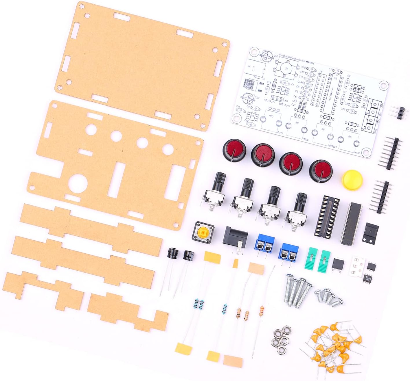
Figure 3.1: All components included in the Weytoll Signal Generator Kit.
4. 組み立て手順
Assembly of this kit requires basic soldering skills and tools (soldering iron, solder, wire cutters, multimeter recommended). Follow the steps below carefully.
- コンポーネントの識別: Before soldering, identify all components using the provided circuit diagram (if included, otherwise refer to component markings). Sort resistors by value, capacitors by type and value, and identify integrated circuits (ICs).
- 最初に小さい部品をはんだ付けする: Begin by soldering the smallest components to the PCB, such as resistors and diodes, followed by capacitors, IC sockets (if using), and then the ICs themselves. Pay attention to polarity for diodes, electrolytic capacitors, and ICs.
- Install Larger Components: Solder the larger components like potentiometers, connectors (power jack, output terminals), and switches. Ensure they are flush with the PCB and correctly oriented.
- Verify Soldering: After all components are soldered, carefully inspect all solder joints for bridges, cold joints, or missing connections. Use a multimeter to check for continuity where appropriate.
- Assemble Acrylic Casing:
- Remove protective film from both sides of the acrylic panels.
- Attach the bottom acrylic panel to the PCB using the provided standoffs and screws.
- Align the top acrylic panel, ensuring all potentiometers, switches, and connectors fit through their respective openings. Secure with the remaining screws.
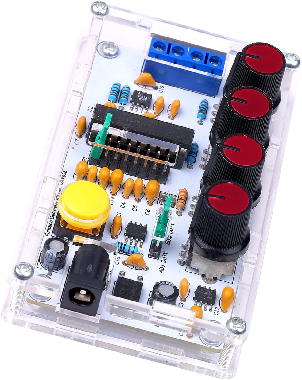
Figure 4.1: Fully assembled signal generator kit.
5. セットアップ
Once assembled, follow these steps to set up your signal generator:
- 電源接続: Connect a DC power supply (9V to 15V) to the power input jack. Ensure correct polarity.
- 出力接続: Connect the signal output (OUT) to your desired measurement device (e.g., oscilloscope, frequency counter) using appropriate cables. The SYNC OUT provides a synchronization signal.
- 初期設定: Before powering on, set all potentiometer knobs to their center positions or minimum values to avoid unexpected outputs.
6. 操作手順
The Weytoll Signal Generator Kit allows for adjustment of frequency, duty cycle, DC offset, and amplitude. It can generate sine, square, triangular, and sawtooth waveforms.
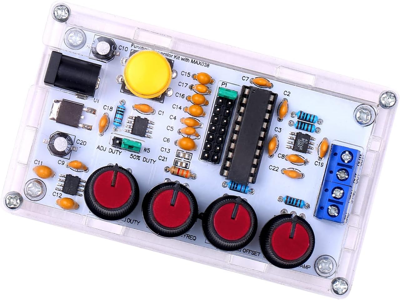
Figure 6.1: Control knobs for signal adjustment.
- Frequency Adjustment (FREQ): Use the FREQ knob to adjust the output frequency from 1Hz to 20MHz.
- Duty Cycle Adjustment (DUTY): Use the DUTY knob to adjust the duty cycle of square and sawtooth waves from 15% to 85%.
- DC Offset Adjustment (OFFSET): The OFFSET knob allows for adjusting the DC offset of the output signal from -5V to +5V.
- Amplitude Adjustment (AMP): 使用 AMP knob to adjust the peak-to-peak amplitude of the output signal from 0.1VPP to 9.5VPP (with a 9V operating voltage)。
- 波形の選択: The kit supports output of triangular, square, sine, and forward/reverse sawtooth waves. Refer to the PCB markings or a detailed circuit diagram for specific waveform selection points or switches, if present.
- Synchronization Output (SYNC OUT): This terminal provides a synchronization signal, useful for triggering oscilloscopes or other external devices.
7. メンテナンス
The Weytoll Signal Generator Kit requires minimal maintenance:
- クリーニング: デバイスを清潔に保ち、ほこりを取り除いてください。清掃には柔らかく乾いた布を使用してください。液体洗剤は使用しないでください。
- ストレージ: Store the device in a dry, cool environment when not in use.
- 検査: Periodically inspect the connections and solder joints for any signs of wear or damage.
8。 トラブルシューティング
If you encounter issues with your signal generator, refer to the following troubleshooting guide:
| 問題 | 考えられる原因 | 解決 |
|---|---|---|
| 出力信号なし |
|
|
| Incorrect frequency/waveform |
|
|
| 歪んだ波形 |
|
|
これらの解決策を試しても問題が解決しない場合は、カスタマー サポートにお問い合わせください。
9. 仕様
The following are the technical specifications for the Weytoll Signal Generator Kit:
| パラメータ | 価値 |
|---|---|
| モデル番号 | XXI0262789081113FJ |
| 材料 | PCB + Acrylic |
| 周波数調整範囲 | 1Hz〜20MHz |
| デューティサイクル調整範囲 | 15%~85% |
| Low Loss True Sine Wave | 0.75% |
| Triangular Wave Output Linearity | 0.1% |
| Low Impedance Output Buffer | 0.1Ω |
| Adjustable DC Offset | -5V~5V |
| 調整可能出力 Ampリチュード | 0.1VPP ~ 9.5VPP (with 9V operating voltage) |
| 電源動作電圧tage | 9V〜15V DC |
| 温度ドリフト | 200ppm/℃ |
| 商品の寸法 (長さ x 幅 x 高さ) | 99 x 59 x 32 mm (3.90 x 2.32 x 1.26 インチ) |
| アイテム重量 | 82グラム |
| パッケージ寸法 | 17.78 x 15.24 x 1.78 cm(7 x 6 x 0.7インチ) |
| パッケージ重量 | 89グラム |

Figure 9.1: Physical dimensions of the signal generator.
10. 保証とサポート
Warranty information for the Weytoll Signal Generator Kit is not explicitly provided in the product details. Please refer to your purchase documentation or contact the seller directly for warranty terms and conditions.
For technical support or inquiries regarding assembly and operation, please contact Weytoll customer service through the retailer's platform or their official webサイト(利用可能な場合)