
1. はじめに
The diymore LCR-TC1 is a versatile multi-function transistor tester designed for automatic detection and measurement of various electronic components. This device can identify NPN and PNP transistors, N-channel and P-channel MOSFETs, diodes (including double diodes), thyristors, resistors, capacitors, and inductors. It features a full-color display for clear readings and is powered by a built-in lithium battery for convenience. This manual provides detailed instructions for the safe and effective use of your LCR-TC1 tester.
2. 安全情報
- Always ensure the component under test is fully discharged before connecting it to the tester, especially capacitors. Failure to do so can damage the tester.
- 充電入力ボリュームtage is 4.5V. Do not use an over-voltage charger, as this will damage the tester's internal circuitry.
- コンポーネントが通電中の回路に接続されている間は、コンポーネントをテストしないでください。
- デバイスを水や極端な温度から遠ざけてください。
- cを開けないでくださいasing of the device unless you are a qualified technician.
3.製品オーバーview
The diymore LCR-TC1 Multi-Function Tester is equipped with a clear display and intuitive controls for easy operation. Below is an illustration of the main components and their functions.

図3.1: LCR-TC1 Tester with labeled parts including 160x128 TFT display, IR receiver window, multi-function key, Start button, transistor test area, Zener diode test area, Micro USB charging interface, and charge indicator LED.
- 160x128 TFT Display: テスト結果とデバイスのステータスを表示します。
- 赤外線受信ウィンドウ: Used for decoding Hitachi-style IR remote control signals.
- 多機能キー: For navigating menus or selecting options (if applicable).
- スタートボタン: Initiates the component test.
- トランジスタテストエリア: ZIF (Zero Insertion Force) socket for connecting components with multiple pins (e.g., transistors, ICs). Numbered pins (1, 2, 3) correspond to test points.
- ツェナーダイオードテスト領域: ツェナーダイオードをテストするための専用エリア。
- マイクロUSB充電インターフェース: 内蔵リチウム電池を充電します。
- 充電インジケーターLED: バッテリーが完全に充電されると緑色に点灯します。
4. 仕様
The following table outlines the key performance parameters and general specifications of the diymore LCR-TC1 Multi-Function Transistor Tester.
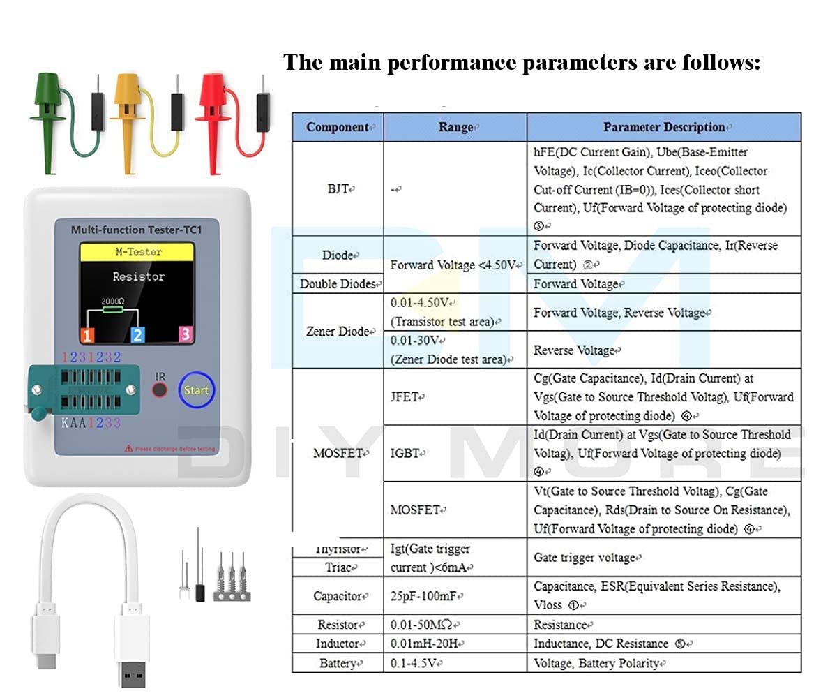
図4.1: Main performance parameters including component types (BJT, Diode, Double Diodes, Zener Diode, JFET, MOSFET, IGBT, Thyristor/Triac, Capacitor, Resistor, Inductor, Battery) and their respective measurement ranges and parameter descriptions.
| パラメータ | 価値 |
|---|---|
| ブランド | DIYモア |
| モデル番号 | LCR-TC1 |
| 電源 | Battery Powered (Built-in Lithium Battery) |
| 最小稼働量tage | 4.5 Volts (Charging Input) |
| 最大稼働量tage | 4.5 Volts (Charging Input) |
| 測定タイプ | LCRメーター |
| アイテム重量 | 0.12キログラム |
| 原産国 | 中国 |
| 含まれるコンポーネント | Transistor Meter |
5. セットアップ
Before using your LCR-TC1 tester for the first time, ensure it is adequately charged.
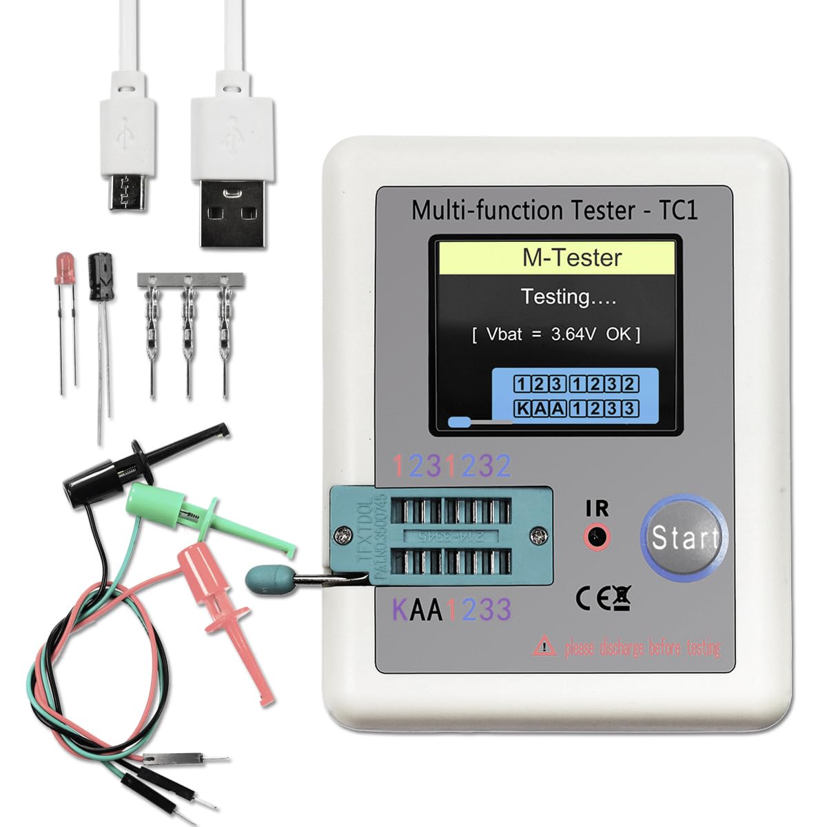
図5.1: LCR-TC1 tester shown with a Micro USB charging cable and various test clips, indicating readiness for use or charging.
- バッテリーの充電: Connect the provided Micro USB cable to the charging interface on the tester and to a 4.5V USB power adapter (not included). The charge indicator LED will show the charging status. It will turn green when fully charged. Avoid using chargers with voltageが4.5Vを超える。
- 初回電源オン: Press the "Start" button to power on the device. The display will light up, and the tester will perform a self-check.
- テストリードの接続: For components that cannot be inserted directly into the ZIF socket, use the included test clips. Connect the clips to the corresponding test points (1, 2, 3) on the tester.
6. 操作手順
The LCR-TC1 tester is designed for automatic component identification and measurement. Follow these steps for testing various components.
6.1. General Testing Procedure
- Ensure the component to be tested is discharged, especially capacitors.
- Connect the component to the tester. You can use the ZIF socket for multi-pin components or the test clips for others. Ensure good contact between the component leads and the test points (1, 2, or 3).
- Press the "Start" button. The tester will automatically identify the component type and measure its parameters.
- The results will be displayed on the TFT screen.
- The device has an automatic shutdown function to conserve battery. It will power off after approximately 20 seconds of inactivity.
6.2. Testing Specific Components

図6.1: Visual representation of the LCR-TC1 tester's capability to measure Inductance, Capacitance, Diode characteristics, and Resistance, showing typical component connections.
- 抵抗器: Connect the resistor leads to any two of the test points (1, 2, or 3). The tester will display the resistance value.
- コンデンサ: Connect the capacitor leads to any two of the test points (1, 2, or 3). Ensure the capacitor is discharged before testing. The tester will display capacitance, ESR (Equivalent Series Resistance), and Vloss.
- インダクタ: Connect the inductor leads to any two of the test points (1, 2, or 3). The tester will display the inductance value and DC resistance.
- Diodes (including Double Diodes): Connect the diode leads to any two test points. The tester will identify the diode type and display forward voltage and reverse current.
- Transistors (NPN, PNP, MOSFET, JFET, IGBT): Insert the transistor leads into the ZIF socket, ensuring each lead (Emitter, Base, Collector for BJT; Source, Gate, Drain for FET) connects to a different test point (1, 2, or 3). The tester will identify the type, pinout, and measure parameters like hFE, Ube, Vt, Cgs, etc.

図6.2: A MOSFET connected to the LCR-TC1 tester using test clips, demonstrating how to test multi-pin components that may not fit the ZIF socket directly.
- Thyristors and Triacs: Connect the leads to test points. The tester will identify the component and its gate trigger current.
- ツェナーダイオード: Use the dedicated Zener diode test area for accurate measurements of Zener voltage.
- IR Remote Control Signals: Point a Hitachi-style IR remote control towards the IR receiver window and press a button. The tester will attempt to decode and display the signal.
7. メンテナンス
- クリーニング: テスターの外側は、柔らかく乾いた布で拭いてください。研磨剤入りの洗剤や溶剤は使用しないでください。
- ストレージ: デバイスは直射日光や極端な温度を避け、涼しく乾燥した場所に保管してください。
- バッテリーのケア: バッテリーの状態を維持するために、デバイスを頻繁に使用していない場合でも、定期的にバッテリーを充電してください。バッテリーを長期間完全に放電することは避けてください。
8。 トラブルシューティング
| 問題 | 考えられる原因 | 解決 |
|---|---|---|
| デバイスの電源が入りません。 | バッテリー残量が少ない、または消耗しています。 | Charge the device using a 4.5V Micro USB charger. |
| Incorrect or no reading displayed. | Poor connection to component; Component not discharged; Component is faulty. | Ensure component leads are clean and securely connected. Discharge capacitors before testing. Test a known good component to verify tester functionality. |
| Tester shuts off too quickly. | 自動シャットダウン機能が有効になりました。 | This is normal behavior to save battery. Press "Start" to reactivate. |
| バッテリーが充電されません。 | Aging battery; Incorrect charging voltage. | Ensure you are using a 4.5V charger. If the issue persists, the internal battery may need replacement by a qualified technician. |
9.サポートと保証
For any questions, technical assistance, or if you require further support regarding your diymore LCR-TC1 Multi-Function Transistor Tester, please contact the manufacturer or seller via email. Refer to your purchase documentation for specific contact details.
Regarding warranty, the product typically comes with a 10-day replacement policy. Please consult your retailer or purchase platform for the most accurate and up-to-date warranty information and terms of service.