
導入
This manual provides essential information for the safe and proper installation, operation, and maintenance of your Veepeak 30 Amp Flanged Outlet NEMA L14-30R Locking Receptacle. Please read all instructions carefully before installation and use. Retain this manual for future reference.
安全情報
警告: Electrical shock hazard. Improper installation or use can result in serious injury or death. Always follow local electrical codes and consult a qualified electrician if you are unsure about any part of the installation process.
- Always disconnect power at the circuit breaker or fuse box before installing or servicing this device.
- Ensure all wiring connections are secure and correct according to the wiring diagram and local codes.
- デバイスの指定された電気定格を超えないでください。
- This product is designed for use with NEMA L14-30P compatible plugs only.
- Keep the weatherproof cap closed when the outlet is not in use to protect against moisture and dust.
パッケージ内容
- 1 x Veepeak 30 Amp NEMA L14-30R Flanged Outlet
- 取り付けネジ
仕様
| 仕様 | 価値 |
|---|---|
| Amp怒る | 30 Amps |
| 巻tage | 125/250ボルトAC |
| NEMA構成 | L14-30R |
| Poles / Wires | 3極4線接地 |
| 最大荷重 | 7500ワット |
| 推奨ワイヤゲージ | 10AWG/4C |
| 材料 | ポリ塩化ビニル(PVC) |
| 認定資格 | ETL Listed (Conforms to UL & CSA standards) |
| 必要な穴のサイズ | 2.5インチ |
セットアップとインストール
必要なツール: Screwdriver, wire strippers, drill (for mounting hole), appropriate drill bit.
- 取り付け場所の準備: Choose a suitable, dry location for installation. Drill a 2.5-inch diameter hole for the receptacle body. Ensure there is enough space behind the mounting surface for wiring connections.
- 配線接続:
Refer to the wiring diagram below and the color-coded terminals on the back of the receptacle. Strip approximately 1/2 inch of insulation from each wire. Insert the wires into the corresponding terminals and tighten the screws securely. Ensure no bare wire strands are exposed outside the terminals.

画像: 背面 view of the L14-30R outlet, displaying the four color-coded terminals for wiring connections (Green for Ground, White for Neutral, Red and Black for Hot).

Image: NEMA L14-30R configuration diagram. 'X' and 'Y' are hot lines (125V each to neutral, 250V between them), 'W' is neutral, and 'G' is ground.
- 緑(G): アース線。
- 白(W): 中性線。
- Black (X): Hot wire (Line 1).
- Red (Y): Hot wire (Line 2).
- レセプタクルを取り付けます。 Insert the receptacle body into the drilled hole. Secure the flanged outlet to the mounting surface using the provided screws. Ensure it is flush and stable.
- 電力を回復する: Once installation is complete and all connections are verified, restore power at the circuit breaker.
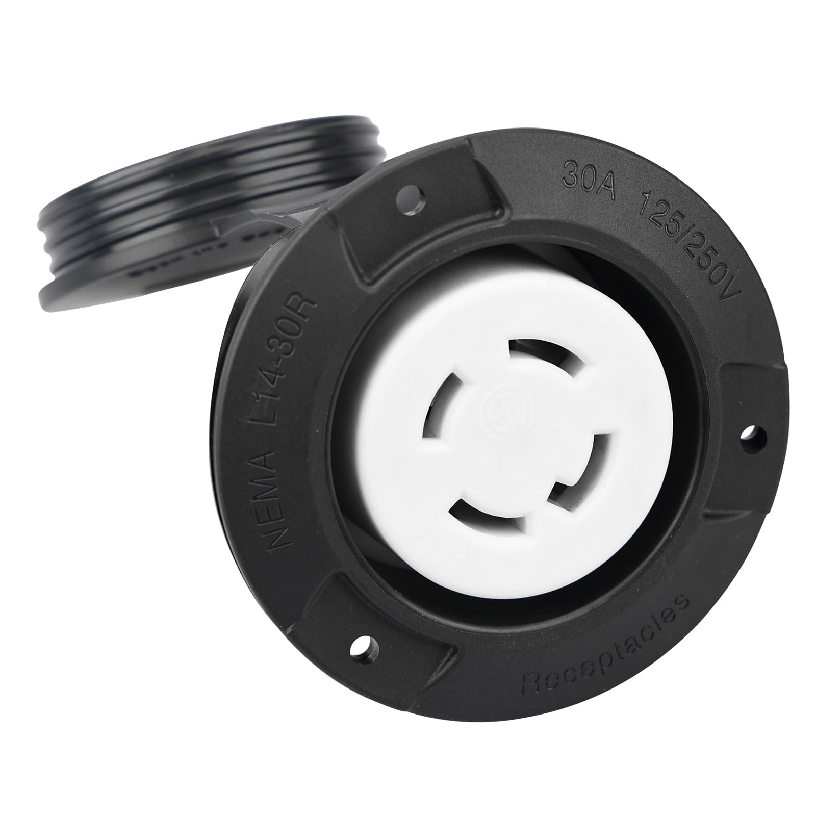
画像: 正面 view of the Veepeak L14-30R flanged outlet with its weatherproof cap open, revealing the NEMA L14-30R locking receptacle.
操作手順
- Opening the Cap: Lift the weatherproof cap to access the receptacle.
- Connecting a Plug: Align the NEMA L14-30P plug with the receptacle. Insert the plug and twist clockwise to lock it into place. Ensure the plug is fully seated and locked.
- Disconnecting a Plug: Twist the plug counter-clockwise to unlock, then pull it straight out from the receptacle.
- Closing the Cap: When the outlet is not in use, ensure the weatherproof cap is securely closed over the receptacle to protect it from environmental elements like rain, snow, and dust.

画像: 正面 view of the Veepeak L14-30R flanged outlet with its weatherproof cap securely closed, providing protection.
メンテナンス
定期的なメンテナンスにより、最適なパフォーマンスと安全性が確保されます。
- クリーニング: Periodically clean the exterior of the outlet with a damp cloth. Do not use abrasive cleaners or solvents. Ensure the cap is closed during cleaning.
- 検査: Regularly inspect the outlet for any signs of damage, wear, or corrosion. Check the weatherproof cap for proper sealing.
- 接続チェック: Annually, or if issues arise, disconnect power and check the wiring connections for tightness. Loose connections can cause overheating.
トラブルシューティング
- 電源なし:
- 回路のブレーカーまたはヒューズを確認してください。トリップしている場合はリセットしてください。
- 電源がアクティブであることを確認します。
- プラグがコンセントに完全に挿入され、ロックされていることを確認してください。
- 緩い接続:
- If the plug feels loose or power is intermittent, disconnect power and inspect the wiring connections at the back of the receptacle for tightness.
- Inspect the plug on the appliance for damage.
- Damage to Outlet:
- If the outlet housing or terminals show signs of damage, cracking, or burning, discontinue use immediately and replace the unit.
トラブルシューティング手順を実行しても問題が解決しない場合は、資格のある電気技師に相談してください。
保証とサポート
Veepeak provides a one-year hassle-free replacement warranty for this product. For warranty claims or customer service inquiries, please contact Veepeak customer support through the retailer where the product was purchased or visit the official Veepeak webサイト。


