
1. はじめに
The UNI-T UT526 is a multifunction electrical installation tester designed for comprehensive electrical system analysis. It accurately measures insulation resistance, RCD (Residual Current Device) status, low resistance continuity, and AC/DC voltage. This device is suitable for testing power distribution systems, lightning protection systems, and wiring systems to ensure safe operation and compliance with electrical standards.

図1: 前面 view of the UNI-T UT526 Multifunction Electrical Installation Tester.
2. 安全情報
Before operating the UT526, read and understand all safety warnings and operating instructions. Failure to follow these instructions may result in electric shock, fire, or serious injury. Keep this manual for future reference.
- 使用する前に、デバイスが良好な動作状態であることを必ず確認してください。
- テスターが破損しているように見える場合、またはテスト リードが損傷している場合は、テスターを使用しないでください。
- Verify the correct function of the tester on a known voltag使用前と使用後のソース。
- 地域および国の安全規則をすべて遵守してください。
- 安全メガネや絶縁手袋などの適切な個人用保護具 (PPE) を着用してください。
- Avoid working alone when performing electrical tests.
- いずれの機能でも最大入力定格を超えないでください。
- Ensure the circuit under test is de-energized and locked out before making connections for resistance or continuity measurements.
3. パッケージ内容
Carefully unpack the box and ensure all items listed below are present and undamaged. If any item is missing or damaged, contact your supplier immediately.
- 1 x UT526 Earth Resistance Tester
- テストリードセット x 1
- 1 x Alligator Clip Set
- 英語マニュアル x 1
- 1 xショルダーストラップ
- キャリーバッグ x 1。
- カラーボックス x 1
Note: Batteries are not included and must be purchased separately (1.5V AA batteries x 6).
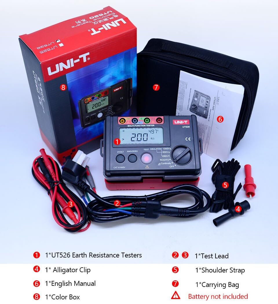
Figure 2: Included components of the UT526 package.
4 製品の特徴
The UNI-T UT526 offers a range of features for reliable electrical installation testing:
- 表示数: 10000 for precise readings.
- 手動範囲: Allows for specific range selection.
- Phase Switch (RCD): Supports 0° and 180° phase testing.
- 低バッテリー表示: 電池の交換が必要な場合に警告します。
- 自動AC/DCボリュームtage 識別: Simplifies voltage 測定値。
- Red Warning Lights: Visual alert for hazardous conditions.
- 認定: CE、UKCA 準拠。
5. セットアップ
Before first use, install the batteries and prepare the test leads.
5.1 バッテリーの取り付け
- デバイスの背面にあるバッテリー コンパートメントを見つけます。
- ドライバーを使用して電池カバーを開けます。
- Insert 6 x 1.5V AA batteries, observing the correct polarity.
- バッテリーカバーを元に戻し、ネジで固定します。
5.2 テストリードの接続
Connect the test leads to the appropriate input terminals on the UT526. The terminals are color-coded and labeled for clarity (e.g., LINE, N, E, L).
6. 操作手順
The UT526 offers various measurement functions. Select the desired function using the rotary switch.
6.1 Measuring Insulation Resistance
This function measures the insulation resistance of electrical circuits and equipment.
- Turn the rotary switch to one of the insulation test voltage settings: 100V, 250V, 500V, or 1000V.
- Insert test leads into the input terminals (Red to LINE, Black to N) and connect them to the circuit under test. High voltageはLINE端子から出力されます。
- For continuous measurement, press the テスト button. The tester will self-lock, output the test voltage, and emit a warning light simultaneously.
- Once the measurement is finished, press テスト again to unlock and stop the continuous measurement.
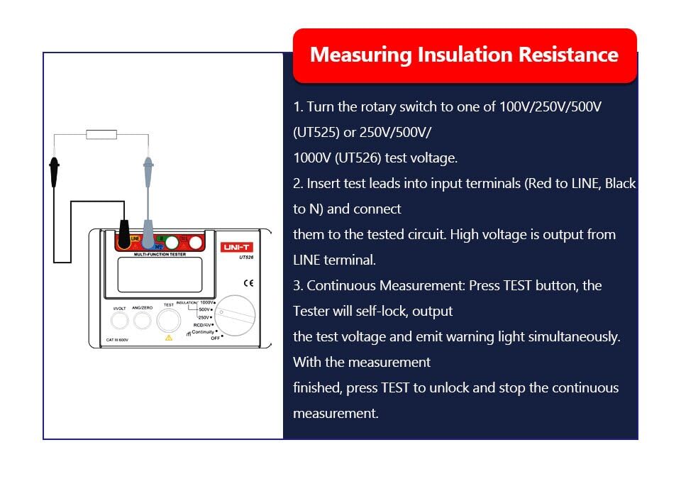
Figure 3: Setup for measuring insulation resistance.
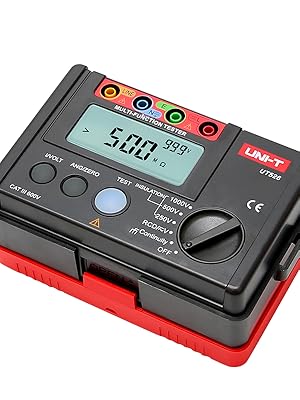
Figure 4: UT526 performing an insulation resistance test with warning light activated.
6.2 RCDテスト(残留電流装置)
The RCD test function verifies the proper operation of Residual Current Devices, ensuring they trip within specified parameters.
- Turn the rotary switch to the RCD function.
- Connect the test leads to the appropriate terminals of the RCD or circuit.
- Select the desired test current and phase (0° or 180°) using the function buttons.
- Initiate the test. The device will measure the trip time and display the result.
Video 1: Demonstration of the RCD test function using the UNI-T UT526. This video shows the connection and operation of the RCD test, illustrating how the device measures the trip time of a residual current device.

Figure 5: UT526 connected for an RCD test.
6.3 Low Resistance Continuity Measurement
This function checks for continuity in circuits and measures low resistance values.
- Turn the rotary switch to the Continuity function.
- Connect the test leads across the component or circuit to be tested.
- The display will show the resistance value. An audible beep indicates continuity (typically below a certain resistance threshold).

Figure 6: UT526 performing a low resistance continuity test on a motor.
6.4 AC/DC ボリュームtag測定
The UT526 can measure both AC and DC voltages。
- ロータリースイッチをV(Voltage) function. The device will automatically identify AC or DC voltage.
- Connect the test leads in parallel with the circuit or component where voltage を測定する必要があります。
- ディスプレイには測定されたボリュームが表示されますtage値。
6.5 Ground Resistance Measurement
While the UT526 is primarily a multifunction electrical installation tester, it also supports ground resistance measurements.
- Turn the rotary switch to the appropriate ground resistance setting (if available, or use continuity for basic checks).
- Connect the test leads according to the specific ground resistance testing method (e.g., 3-pole or 4-pole method, if supported by the model).
- Initiate the measurement and read the ground resistance value from the display.

Figure 7: UT526 connected for ground resistance testing.
7. メンテナンス
適切なメンテナンスにより、UT526 テスターの寿命と精度が保証されます。
- クリーニング: 広告でデバイスをワイプamp cloth and mild detergent. Do not use abrasive cleaners or solvents. Ensure the device is dry before storage.
- バッテリー交換: 電池残量が少なくなった場合は、速やかに電池を交換してください。長期間使用しない場合は、液漏れを防ぐため、電池を取り外してください。
- ストレージ: テスターは直射日光や極端な温度を避け、涼しく乾燥した場所に保管してください。付属のキャリーバッグに入れて保護してください。
- 較正: プロフェッショナル用途の場合、測定精度を維持するために、認定サービス センターによる定期的な校正をお勧めします。
8。 トラブルシューティング
UT526 で問題が発生した場合は、次の一般的な問題と解決策を参照してください。
| 問題 | 考えられる原因 | 解決 |
|---|---|---|
| デバイスの電源が入らない | 電池切れまたは電池の取り付け間違い | 正しい極性を確認して電池を交換してください。 |
| 不正確な測定値 | Poor test lead connection, out of calibration, environmental interference | Ensure secure connections. Check against a known source. Consider professional calibration. |
| RCD test fails to trip | Faulty RCD, incorrect test parameters, wiring issue | Verify RCD functionality independently. Check test current and phase settings. Inspect circuit wiring. |
| ディスプレイに「OL」(過負荷)と表示される | Measurement exceeds selected range or device capability | Select a higher range or ensure the measurement is within the device's specifications. |
9. 仕様
Detailed technical specifications for the UNI-T UT526 Multifunction Electrical Installation Tester are provided below.

Figure 8: Comprehensive specifications for the UT526.
| 仕様 | 価値 |
|---|---|
| ブランド | ユニット |
| モデル | HY-UT526 |
| 電源 | Battery Powered (6 x 1.5V AA) |
| アイテム重量 | 0.6キロ |
| アイテムの寸法 | 6.5 x 4.33 x 4.72インチ |
| 仕様が満たされました | CE, ISO 9001, RoHS, UKCA |
| 表示数 | 10000 |
| 絶縁抵抗試験 Voltages | 100V、250V、500V、1000V |
| RCD Phase Switch | 0°と180° |
| 低バッテリー表示 | はい |
| 自動AC/DCボリュームtage Identification | はい |
| 赤色警告灯 | はい |
10. 保証
The UNI-T UT526 Multifunction Electrical Installation Tester comes with a 1年間保証 from the date of purchase. This warranty covers defects in materials and workmanship under normal use. It does not cover damage caused by misuse, accident, unauthorized modification, or neglect. Please retain your proof of purchase for warranty claims.
11. サポート
For technical assistance, troubleshooting beyond this manual, or warranty inquiries, please contact UNI-T customer support. Refer to the official UNI-T web最新の連絡先情報については、サイトまたは製品パッケージをご覧ください。
UNI-T公式 Webサイト: www.uni-trend.com


