
PowMr ML2440
PowMr 40A MPPT ソーラー充電コントローラー ユーザーマニュアル
モデル: ML2440
1. はじめに
This manual provides essential information for the safe and efficient operation of your PowMr 40A MPPT Solar Charge Controller, model ML2440. Please read this manual thoroughly before installation and use to ensure optimal performance and longevity of the product.
2. 安全に関する注意事項
- ショートや損傷を防ぐために、すべての配線が正しく接続され、固定されていることを確認してください。
- Always connect the battery to the charge controller first, then the solar panels, and finally the load. Disconnect in the reverse order.
- コントローラーをご自身で修理または改造しないでください。修理は資格のある担当者にご相談ください。
- コントローラーは、可燃性物質や直射日光を避け、換気の良い場所に設置してください。
- 電気システムを扱うときは、適切な個人用保護具 (PPE) を着用してください。
- システムボリュームを確認するtage matches the controller's specifications (12V/24V auto-detection).
3.製品オーバーview
The PowMr 40A MPPT Solar Charge Controller is designed to efficiently manage power from your solar panels to charge various battery types, including Lithium, Sealed, Gel, and Flooded batteries. It features Maximum Power Point Tracking (MPPT) technology for optimized solar energy harvesting, automatic 12V/24V system voltage detection, and a clear LCD display for monitoring system status.
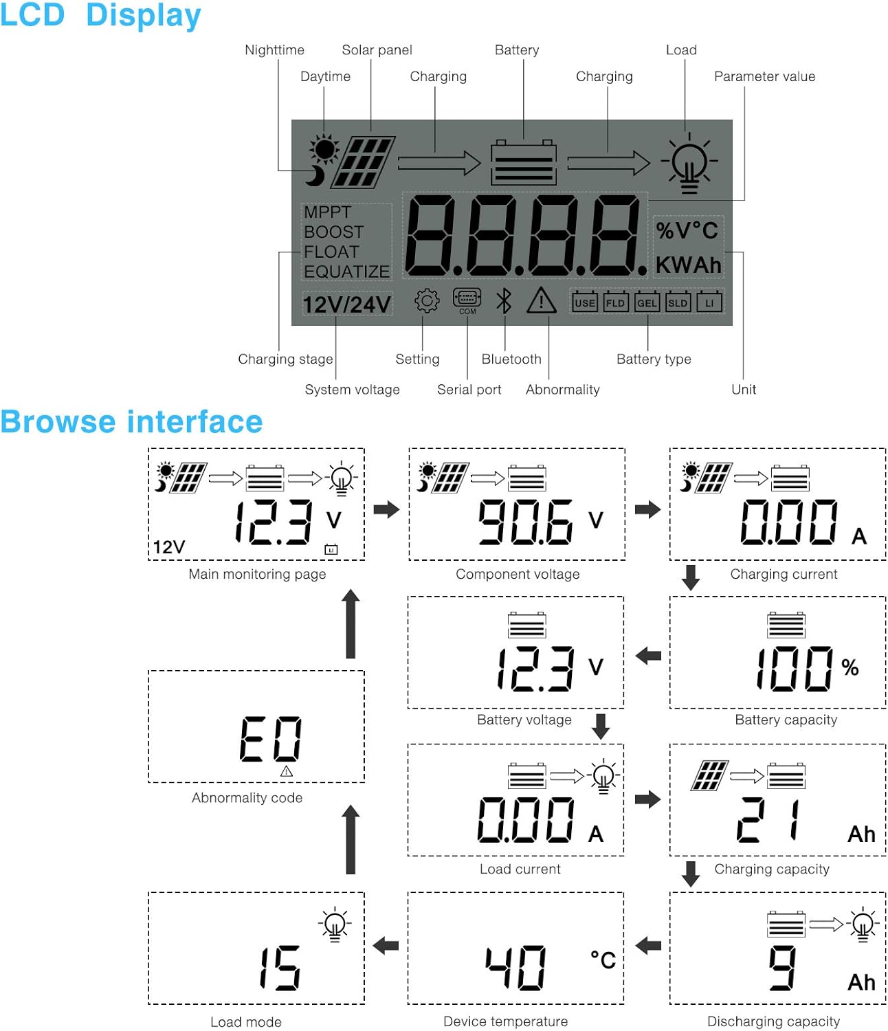
図3.1: フロント view PowMr 40A MPPT ソーラー充電コントローラー。
This image shows the main unit of the PowMr 40A MPPT Solar Charge Controller, highlighting its compact design and integrated LCD screen.
The controller supports a maximum solar input voltage of 100V and a maximum input power of 1100W for a 24V system (550W for 12V). It also includes temperature compensation for accurate charging across varying environmental conditions.

図3.2: Temperature compensation feature.
This image illustrates the temperature compensation capability of the controller, ensuring optimal battery charging performance in both hot and cold environments.
4.設置と配線
ソーラー充電コントローラーを安全かつ効率的に動作させるには、適切な設置が不可欠です。以下の手順を慎重に実行してください。
4.1 配線図

図4.1: Wiring diagram for the PowMr MPPT Solar Charge Controller.
This diagram illustrates the correct connection order for the battery, solar panels, DC load, and optional inverter. A temperature sensor is also shown.
4.2 接続手順
- まずバッテリーを接続します: Connect the battery to the charge controller's battery terminals. Ensure correct polarity. The controller will auto-detect 12V or 24V system voltage.
- ソーラーパネルを接続する: Connect the solar panels to the PV input terminals. Ensure correct polarity. The controller will begin charging if sufficient sunlight is available.
- DC負荷を接続する(オプション): If using a DC load directly from the controller, connect it to the load terminals.
- インバータを接続する(オプション): If using an inverter, connect it to the battery terminals (not directly to the load terminals of the controller).
- 温度センサーを接続します: For accurate temperature compensation, connect the provided temperature sensor to the designated port on the controller and place the sensor near the battery.
切断命令: To disconnect the system, always follow the reverse order: Disconnect load, then solar panels, then battery.
5. 操作手順
This section details how to monitor and configure your charge controller using its integrated LCD display and the optional Bluetooth mobile application.
5.1 LCD 表示オーバーview

図5.1: LCD Display and Browse Interface.
This image shows the various icons and parameters displayed on the LCD screen, along with the navigation flow through different monitoring pages.
LCDディスプレイには、太陽光発電システムに関するリアルタイムの情報が表示されます。主な指標は以下の通りです。
- 充電Stage: MPPT, Boost, Float, Equalize.
- システム巻tage: 12V/24V auto-detected.
- 電池のタイプ: Icons for Lithium (Li), Sealed (SLD), Gel (GEL), Flooded (FLD).
- ステータスインジケータ: Solar panel activity, battery charging, load status, abnormality.
- パラメータ値: ボリュームを表示tage, current, capacity, temperature, etc.
Use the buttons below the LCD to navigate through different screens to view parameters such as main monitoring page, component voltage、充電電流、バッテリー容量tage, battery capacity, load current, charging capacity, device temperature, discharging capacity, abnormality codes, and load mode.
5.2 Bluetooth Mobile Application
The controller supports an optional Bluetooth module (BT-1) for remote monitoring and parameter adjustment via a mobile application (available for Apple iOS and Android devices). The Bluetooth module connects to the RS232 port on the controller.

図5.2: Controller with optional Bluetooth module.
This image displays the PowMr MPPT Solar Charge Controller alongside its optional BT-1 Bluetooth communication module and connecting cable.

図5.3: BT-1 Bluetooth module.
詳細な view of the BT-1 Bluetooth module, which enables wireless communication with the solar charge controller for remote monitoring and settings adjustments.

図5.4: Bluetooth Mobile Interface Display.
This image shows various screens from the mobile application, including real-time monitoring, data records, energy records, and parameter settings.
The mobile application allows you to:
- Monitor real-time system data (voltage, current, power, temperature).
- View historical data and energy records.
- Adjust various charging parameters and battery settings.
- 工場出荷時のデフォルト設定に戻します。
6. メンテナンス
Regular maintenance ensures the longevity and optimal performance of your charge controller.
- クリーニング: コントローラーの外側は定期的に乾いた布で埃やゴミを拭き取ってください。通気口にゴミが付着していないことを確認してください。
- 接続: Annually check all wiring connections for tightness and corrosion. Loose connections can cause overheating and poor performance.
- 環境: 設置環境が指定された動作温度範囲内にあり、過度の湿気やほこりがないことを確認してください。
7。 トラブルシューティング
This section provides guidance for common issues. Refer to the LCD display for abnormality codes.
- ディスプレイなし/電源なし:
- バッテリーの接続を確認し、バッテリーの容量を確認してくださいtage は動作範囲内です。
- バッテリーヒューズ(取り付けられている場合)が損傷していないことを確認します。
- 充電なし:
- ソーラーパネルが正しく接続され、十分な日光が当たっていることを確認します。
- ソーラーパネルの容量を確認するtage と現在。
- Verify that the battery is not fully charged or in a protection state.
- ロードが機能しない:
- Check load connections and ensure the load current does not exceed the controller's rating.
- バッテリーの容量を確認しますtageは低ボラティリティを上回っているtag切断(LVD)設定。
- Check for any abnormality codes on the LCD related to load output.
- Abnormality Codes (e.g., "E0"):
- Refer to the specific abnormality code displayed on the LCD. Consult the full product manual or manufacturer's support for detailed explanations and solutions for each code.
8. 仕様
Technical specifications for the PowMr 40A MPPT Solar Charge Controller (Model ML2440).

図8.1: 製品仕様表。
This table provides detailed technical parameters for the ML2420, ML2430, and ML2440 models. The ML2440 column is relevant for this 40A controller.
| パラメータ | Value (ML2440) |
|---|---|
| モデル | ML2440 |
| システムvoltage | 12V / 24V自動 |
| 無負荷損失 | 0.7 W〜1.2 W |
| バッテリーvoltage | 9~35V |
| 最大ソーラーインプットvoltage | 100V(25°C)、90V(-25°C) |
| 最大パワーポイントvoltage範囲 | バッテリーvoltage + 2V〜75V |
| 定格充電電流 | 40A |
| 定格負荷電流 | 20A |
| 最大容量性負荷容量 | 10000uF |
| 最大太陽光発電システムの入力電力 | 550W/ 12V, 1100W/ 24V |
| 変換効率 | ≤ 98% |
| MPPT追跡効率 | > 99% |
| 温度補償係数 | -3.0mv/ °C/ 2V (default) |
| 動作温度 | -35°C ~ +45°C |
| 保護等級 | IP32 |
| 重さ | 2kg |
| コミュニケーション方法 | RS232 |
| 高度 | ≤ 3000m |
| 製品寸法 | 238*173*72.5ミリメートル |
9. 保証とサポート
For warranty information, please refer to the documentation included with your product packaging or visit the official PowMr website. If you encounter any issues not covered in this manual or require further assistance, please contact PowMr customer support.
PowMr Official Webサイト: AmazonのPowMrストアをご覧ください
Ask a question about this manual
Ask about setup, troubleshooting, compatibility, parts, safety, or missing instructions. Manuals+ will review the question and use this page’s manual context to help answer it.