
iFlight SucceX Mini Force
iFlight SucceX Mini Force 5.8GHz VTX Instruction Manual
Model: SucceX Mini Force
導入
This manual provides comprehensive instructions for the setup, operation, maintenance, and troubleshooting of your iFlight SucceX Mini Force 5.8GHz Video Transmitter (VTX). Please read this manual thoroughly before use to ensure proper functionality and safety.
The iFlight SucceX Mini Force VTX is designed for FPV drone applications, offering adjustable power output and reliable video transmission.
重要な安全上の警告
- VTX is set to 25mW by default. Power levels above 25mW require a HAM license or approval by local authorities.
- Ensure compliance with local regulations regarding frequency usage and power output.
- Always connect the antenna before powering on the VTX to prevent damage.
- Avoid touching the VTX during operation as it can become hot.
- This device is not a toy. Adult supervision is recommended for users under 18.
製品終了view
The iFlight SucceX Mini Force VTX is a compact 5.8GHz video transmitter. It features adjustable power output settings (PIT/25mW/200mW/400mW/600mW) and an MMCX antenna connector. The board includes clearly labeled pads for video input, ground, 5V power, and RX for control.

図1:上 view of the iFlight SucceX Mini Force VTX. This image displays the compact design of the video transmitter, highlighting the central SucceX Mini Force chip, the gold-colored MMCX antenna connector, and various solder pads labeled for video, ground, 5V power, and RX. The power, band, and channel buttons are also visible on the chip's label.

図2: 角度付き view of the iFlight SucceX Mini Force VTX. This perspective provides a clearer look at the MMCX connector and the overall component arrangement on the circuit board.
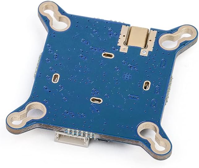
図3:下 view of the iFlight SucceX Mini Force VTX. This image shows the underside of the VTX board, revealing the mounting holes and additional solder points.

図 4: 拡大図 view of the MMCX connector. This detailed image focuses on the gold-plated MMCX connector, which is used for attaching the FPV antenna.
設定
1.配線図
Refer to the following diagram for proper connection of the VTX to your flight controller and camera.

Figure 5: Wiring Diagram. This diagram illustrates how to connect the SucceX Mini Force VTX to other components of an FPV drone, including the camera (Video, GND), power source (5V, GND), and flight controller (RX for OSD control).
- ビデオ: FPV カメラのビデオ出力に接続します。
- GND: Connect to a common ground point.
- + 5V: Connect to a regulated 5V power supply from your flight controller or PDB.
- 処方箋: Connect to a UART TX pad on your flight controller for OSD control (SmartAudio/TrampHV).
2.アンテナ接続
Carefully connect your 5.8GHz FPV antenna to the MMCX connector on the VTX. Ensure a secure connection. Always connect the antenna before applying power to the VTX.
3. Betaflight VTX Tables
For full control over VTX settings via your flight controller's OSD (On-Screen Display) or Betaflight Configurator, it is recommended to set up Betaflight VTX tables. These tables define the available bands, channels, and power levels for your specific VTX.
Refer to the iFlight website or Betaflight documentation for detailed instructions on configuring VTX tables. Ensure you use tables appropriate for your region to comply with local regulations.
操作手順
1. 電源を入れる
Once wired correctly and with the antenna attached, apply power to your drone. The VTX will power on and begin transmitting on its last saved settings.
2. Changing Settings (OSD/Buttons)
Settings such as power level, band, and channel can be adjusted using two primary methods:
- OSD Control (SmartAudio/TrampHV): If configured in Betaflight, you can access the VTX settings menu through your FPV goggles' OSD. Navigate to the VTX section to change power, band, and channel. This is the recommended method for precise control and compliance.
- オンボードボタン: The VTX board features small buttons for manual adjustment.
- 電源ボタン: Short press to cycle through power levels (PIT/25mW/200mW/400mW/600mW).
- バンドボタン: Short press to cycle through frequency bands.
- チャンネルボタン: Short press to cycle through channels within the selected band.
注記: Always verify your selected frequency and power level are legal in your operating region before flight.

Figure 6: Close-up of VTX control buttons. This image provides a detailed view of the small buttons labeled "POWER", "BAND", and "CHANNEL" on the VTX module, used for manual configuration.
メンテナンス
- アンテナセキュリティ: Regularly check that the MMCX antenna connector is securely attached. A loose antenna can lead to poor video quality or VTX damage.
- 清潔さ: Keep the VTX free from dirt, dust, and moisture. Use a soft, dry brush or compressed air for cleaning.
- 物理検査: Periodically inspect the board for any signs of physical damage, loose components, or cold solder joints.
- 熱管理: Ensure adequate airflow around the VTX, especially when operating at higher power levels, to prevent overheating.
トラブルシューティング
| 問題 | 考えられる原因 | 解決 |
|---|---|---|
| ビデオ信号なし / 黒い画面 |
|
|
| ビデオ品質が悪い(ノイズ、線) |
|
|
| VTX gets excessively hot |
|
|
仕様
| 特徴 | 詳細 |
|---|---|
| ブランド | iFlight |
| モデル名 | SucceX Mini Force |
| 頻度 | 5.8GHz |
| 出力 | PIT/25mW/200mW/400mW/600mW (Adjustable) |
| アンテナコネクタ | MMCX |
| 入力ボリュームtage | 5V (typically from flight controller) |
| 制御プロトコル | スマートオーディオ/TrampHV (via RX pad) |
| 寸法 | 29mm×29mm |
| 取付穴間隔 | 20mm×20mm |
| 重さ | 0.634オンス(約18g) |

Figure 7: VTX weight measurement. This image shows the SucceX Mini Force VTX placed on a digital scale, indicating a weight of 4.0 grams. Note that official specifications list the weight as 0.634 ounces (approximately 18 grams).
Figure 8: VTX dimensions. This image displays the top view of the VTX with measurements indicating its length and width are both 29mm. Mounting hole spacing is also indicated as 20mm.
保証とサポート
For warranty information and technical support, please refer to the official iFlight web公式サイトをご覧いただくか、カスタマーサービスに直接お問い合わせください。保証請求の際に必要となりますので、購入証明書を保管してください。
Official iFlight Store: iFlight Amazon Store
Ask a question about this manual
Ask about setup, troubleshooting, compatibility, parts, safety, or missing instructions. Manuals+ will review the question and use this page’s manual context to help answer it.