1. はじめに
This manual provides essential information for the installation, operation, maintenance, and troubleshooting of the Juniper Networks EX4200-24P 24-Port Power over Ethernet (PoE) Ethernet Switch. The EX4200-24P is designed to provide high-performance, reliable network connectivity for enterprise and data center environments, offering 24 Gigabit Ethernet ports with PoE+ capabilities and Layer 3 features.
2. 安全情報
怪我や機器の損傷を防ぐために、次の安全上の注意事項を守ってください。
- デバイスが適切に接地されていることを確認してください。
- 濡れた環境や湿度の高い環境ではスイッチを操作しないでください。
- メンテナンスやインストール手順を実行する前に、電源を切断してください。
- 承認された電源コードとアクセサリのみを使用してください。
- 過熱を防ぐために、スイッチの周囲に十分な換気を確保してください。
3. パッケージ内容
パッケージに次のアイテムが含まれていることを確認してください。
- Juniper Networks EX4200-24P Ethernet Switch
- 電源コード
- ラックマウントキット(ブラケット、ネジ)
- コンソール ケーブル (RJ-45 から DB-9)
- ドキュメント(クイックスタートガイド、安全情報)
Note: Contents may vary based on the specific renewed product offering.
4. フィジカルオーバーview
4.1フロントパネル
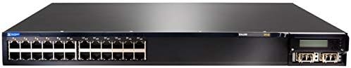
Figure 4.1: Front Panel of EX4200-24P Switch. This image displays the front of the Juniper Networks EX4200-24P switch, featuring 24 RJ-45 Gigabit Ethernet ports, each with LED indicators, and four SFP+ uplink ports on the right side, along with a small LCD display and control buttons.
The front panel of the EX4200-24P switch includes:
- 24 x 10/100/1000BASE-T イーサネット ポート: RJ-45 connectors for network devices. Each port supports Power over Ethernet Plus (PoE+).
- ポートステータス LED: Indicators for link status, activity, and PoE status for each port.
- Uplink Module Slot: Typically houses 4x SFP/SFP+ ports for high-speed uplinks to other network devices or the core network.
- LCDディスプレイ: Provides system status, configuration information, and error messages.
- コントロールボタン: Used to navigate and interact with the LCD display menu.
- システムステータス LED: Indicators for power, alarm, and system status.
4.2 背面パネル

図4.2: 角度付き View of EX4200-24P Switch. This image provides an angled perspective of the Juniper Networks EX4200-24P switch, highlighting the front panel with its 24 Ethernet ports and uplink module, and giving a partial view of the side chassis. The rear panel, not fully visible in this image, typically contains power input, fan modules, and a console port.
背面パネルには通常、次のものが含まれます。
- AC電源コネクタ: 電源コードを接続します。
- コンソールポート(RJ-45): シリアル接続を使用したローカル管理および初期構成用。
- USBポート: ソフトウェアのアップグレードまたは構成のバックアップ/復元用。
- ファンモジュール: Removable fan trays for cooling.
5. セットアップとインストール
5.1 サイトの準備
Before installation, ensure the installation site meets the following requirements:
- 環境: Maintain an ambient temperature between 0°C and 45°C (32°F and 113°F) and relative humidity between 10% and 85% (non-condensing).
- 力: A dedicated power outlet with proper grounding is recommended.
- 換気: Ensure at least 5 cm (2 inches) of clearance at the front and rear for airflow.
5.2ラックへの取り付け
The EX4200-24P is designed for installation in a standard 19-inch equipment rack.
- 付属のネジを使用して、付属のラックマウント ブラケットをスイッチの側面に取り付けます。
- スイッチをラックの支柱に合わせて、適切なラック ネジを使用して固定します。
5.3電源接続
- Connect one end of the power cord to the AC power connector on the rear panel of the switch.
- 電源コードのもう一方の端をアースされた電源コンセントに接続します。
- The switch will power on automatically. Observe the system status LEDs for initial boot-up.
5.4ネットワーク接続
- Connect Ethernet cables from your network devices (computers, IP phones, wireless access points) to the RJ-45 ports on the front panel.
- For uplink connections to other switches or routers, insert appropriate SFP/SFP+ transceivers into the uplink module slot and connect fiber or copper cables as required.
- For initial configuration, connect a console cable from your management workstation to the console port on the rear panel.
6. スイッチの操作
6.1 電源オンと初期ブート
Once connected to power, the switch will begin its boot sequence. The system status LEDs will indicate the boot progress. The LCD display will show system information during startup.
6.2 LEDインジケーター
Monitor the LEDs on the front panel to understand the switch's operational status:
- システムLED: Indicates overall system health (e.g., green for normal operation, amber for minor alarm, red for major alarm).
- 電源LED: 電源の状態を示します。
- ポートリンク/アクティビティ LED:
- 緑色の点灯: リンクが確立されました。
- 緑色に点滅: 港でのアクティビティ。
- オフ: リンクなし。
- PoE ステータス LED: Indicate Power over Ethernet status for PoE-enabled ports.
6.3 基本設定アクセス
The switch can be configured via the command-line interface (CLI) through the console port or remotely via Telnet/SSH after initial IP configuration. Refer to the Juniper Networks documentation for detailed CLI commands and configuration guides.
- コンソールポート: ターミナル エミュレータ (例: PuTTY) を、9600 ボー、8 データ ビット、パリティなし、1 ストップ ビット、フロー制御なしに設定して使用します。
- Web インタフェース: Some Juniper switches offer a web-based management interface. Check your specific firmware version for availability and default access details.
7. メンテナンス
7.1 クリーニング
定期的にクリーニングすると、最適なパフォーマンスが維持され、スイッチの寿命が延びます。
- Power off and disconnect the switch before cleaning.
- 外側を拭くときは、柔らかく乾いた布を使用してください。
- Use compressed air to clear dust from ventilation openings and fan modules.
- スイッチに液体クリーナーやエアゾールクリーナーを直接使用しないでください。
7.2ファームウェアアップデート
定期的にJuniper Networksのサポートを確認してください website for the latest firmware updates. Firmware updates can provide new features, performance improvements, and security patches. Follow the instructions provided with the firmware package for proper installation.
7.3 環境への配慮
Ensure the switch operates within its specified temperature and humidity ranges. Avoid blocking ventilation ports and ensure proper airflow to prevent overheating, which can lead to system instability or failure.
8。 トラブルシューティング
このセクションでは、発生する可能性のある一般的な問題に対する解決策を示します。
8.1 電源なし
- 電源コードがスイッチと電源コンセントの両方にしっかりと接続されていることを確認します。
- 別のデバイスを接続して、電源コンセントが機能するかどうかを確認します。
- Ensure the power supply unit (if modular) is properly seated.
8.2 ポートにリンクがありません
- イーサネットケーブルの両端の接続を確認してください。別のケーブルを試してください。
- 接続されているデバイスの電源がオンになっていて、正しく機能していることを確認します。
- Check the port configuration on the switch (e.g., speed, duplex settings).
8.3 ネットワーク接続の問題
- Confirm the switch has a valid IP address and network configuration.
- ネットワーク上で IP アドレスの競合がないか確認します。
- Verify VLAN configurations if applicable.
- スイッチと接続されているデバイスを再起動します。
8.4 工場出荷時設定へのリセット
A factory reset will erase all configurations and restore the switch to its default settings. Consult the Juniper Networks documentation for the specific procedure for the EX4200 series, as it typically involves a specific command sequence via the console port.
9. 技術仕様
| 特徴 | 仕様 |
|---|---|
| モデル | EX4200-24P |
| ブランド | ジュニパーネットワークス |
| ポート数 | 24 x 10/100/1000BASE-T (PoE+) |
| インターフェースタイプ | RJ45 |
| 製品寸法(長さx幅x高さ) | 23 x 22.75 x 11 インチ (58.42 x 57.78 x 27.94 cm) |
| アイテム重量 | 23.1ポンド(10.48kg) |
| ケース素材 | プラスチック |
| 上限温度定格 | 摂氏45度 |
| 欧州連合 | 647213692099 |
| ASIN | B07PFLPRX6 |
10. 保証情報
This Juniper Networks EX4200-24P switch is offered as a renewed product. Warranty coverage for renewed products is typically provided by the seller, "Network Hardware Depot" in this case, or the Amazon Renewed program, not directly by Juniper Networks.
- Seller's Return Policy: The seller offers a return policy, typically 30 days for refund/replacement.
- 延長保護プラン: Additional protection plans may be available for purchase through Amazon or third-party providers.
- For specific warranty details and terms, please refer to the purchase agreement or contact the seller directly.
Legal Disclaimer from Seller: "We DO NOT accept RMA's or Returns for Non Defective Items. Any merchandise returned for repair and found NOT to be defective by our technicians will have a 25% restocking fee. There will be no exception to this policy. By placing a bid or order with us you have entered into a binding agreement that you acknowledge and accept our procedures. Additional warranty length is available, contact us directly for more details."
11. サポート
For technical assistance, further documentation, or advanced configuration guides, please refer to the official Juniper Networks support website. For issues related to the renewed product's condition or seller-specific policies, contact the seller directly.
- Juniper Networks サポート: www.juniper.net/us/en/support.html
- 販売者連絡先: Refer to your Amazon order details for seller contact information (Network Hardware Depot).