
1. はじめに
The EPEVER 20A MPPT Solar Charge Controller, model Tracer2210AN, is an advanced Maximum Power Point Tracking (MPPT) device designed for 12V/24V automatic work solar systems. It efficiently manages power flow from solar panels to batteries, ensuring optimal charging and extending battery life. This controller features high conversion efficiency, supports various battery types, and offers comprehensive protection functions. This manual provides essential information for the safe installation, operation, and maintenance of your solar charge controller.

Image 1.1: EPEVER 20A MPPT Solar Charge Controller (Tracer2210AN). This image shows the front view of the solar charge controller with its LCD display and control buttons.
2. 安全に関する注意事項
- 常にバッテリーを充電コントローラーに接続してください 初め, then the solar panel, and finally the load. Disconnect in the reverse order: load, then solar panel, then battery.
- 過熱を防ぐために、コントローラーの周囲に適切な換気を確保してください。
- Use appropriate wire gauges for all connections to prevent voltage drop and overheating. Refer to the specifications section for recommended cable sizes.
- Avoid short circuits at all terminals.
- Install the controller in a dry, well-ventilated area, away from direct sunlight and moisture.
- Do not attempt to repair or modify the controller yourself. Refer to qualified personnel for service.
- 設置作業中は、目の保護具や絶縁手袋などの適切な個人用保護具 (PPE) を着用してください。
3.製品オーバーview
The Tracer2210AN controller incorporates advanced features for efficient solar power management:
- 高度なMPPTテクノロジー: Ensures maximum power extraction from solar panels with tracking efficiency not less than 99.5% and a maximum conversion efficiency of 98%.
- 高品質のコンポーネント: Utilizes international famous brands of ST and IR components for reliability and durability.
- バッテリー互換性: Supports various battery types including lead-acid (sealed, gel, flooded) and lithium-ion (LiFePO4, Li(NiCoMn)O2), with user-defined settings.
- 温度補正: Includes battery temperature compensation function for lead-acid batteries.
- リアルタイム監視: Provides real-time energy statistics and supports communication via RS-485 bus with Modbus protocol for monitoring and parameter setting via mobile APP or PC software (requires optional accessories like MT50, WiFi, or BLE adapters).
- 保護機能: Features multiple safety protections including overheating power reduction.
3.1 コントローラコンポーネント

画像3.1:正面 view of the EPEVER Tracer2210AN controller with labeled components. Key components include the LCD display, SELECT and ENTER buttons, remote temperature sensor port, solar panel terminals, battery terminals, load terminals, and an RJ45 communication port.

図3.2: 上部と下部 views of the EPEVER Tracer2210AN controller. The top view shows the model information and certifications, while the bottom view displays the terminal connections and communication port.
4. セットアップ
4.1コントローラーの取り付け
Mount the controller vertically on a wall or a stable surface. Ensure there is sufficient space around the controller for proper air circulation to dissipate heat. The dimensions of the controller are 220mm x 154mm x 52mm.

Image 4.1: EPEVER MPPT 20A Solar Charge Controller with its physical dimensions indicated. The controller measures 220mm in length, 154mm in width, and 52mm in height.
4.2配線接続
Follow the connection order carefully to avoid damage to the controller or other components. Always connect the battery first, then the solar panel, and finally the load. Disconnect in the reverse order.
- バッテリーを接続します。 バッテリーのプラス端子とマイナス端子をコントローラーの対応するバッテリー端子に接続します。極性が正しいことを確認してください。
- ソーラーパネルを接続します。 Connect the positive and negative terminals of the solar panel to the corresponding PV terminals on the controller. Ensure correct polarity.
- 負荷を接続する: Connect the positive and negative terminals of the DC load to the corresponding load terminals on the controller. Ensure correct polarity.
- Connect Remote Temperature Sensor (Optional): If using, connect the RTS300R47K3.81A temperature sensor to the designated port on the controller and attach the sensor to the battery for accurate temperature compensation.

Image 4.2: Connection diagram illustrating the proper wiring sequence for the EPEVER solar charge controller. It shows connections from the solar panel, battery (with fuse), and DC load, as well as an optional inverter for AC loads.
5. 操作手順
5.1 LCDディスプレイとボタン
The controller features an LCD display that shows system status, charging parameters, and error codes. The 'SELECT' and 'ENTER' buttons are used to navigate through menus and adjust settings.
5.2 バッテリータイプの設定
The controller supports various battery types. It is crucial to select the correct battery type for optimal charging and battery longevity. The default setting is 'Sealed' for lead-acid batteries.
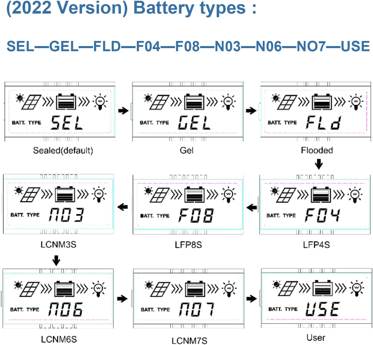
Image 5.1: LCD display showing various battery type selections. Options include Sealed (SEL), Gel (GEL), Flooded (FLD), LiFePO4 (LFP4S, LFP8S), Li(NiCoMn)O2 (LCNM3S, LCNM6S, LCNM7S), and User-defined (USE).
バッテリーの種類を変更するには:
- Press the 'SELECT' button to cycle through the main display screens until you reach the battery type setting.
- Press and hold the 'ENTER' button to enter the setting modification mode.
- Use the 'SELECT' button to choose the desired battery type (e.g., GEL, FLD, LFP4S, USE).
- Press 'ENTER' again to confirm and save the selection.
5.3 監視と通信
The Tracer2210AN controller can be monitored and configured remotely using optional accessories:
- MT50リモートメーター: Connects via RJ45 cable to display real-time data and modify parameters.
- WiFi/BLE Adapters (eBox-WIFI-01, eBox-BLE-01): Connects to the RS-485 port to enable wireless monitoring and control via a mobile application.
- PC Communication Cable (CC-RS485-USB-150U): Connects to a PC for monitoring and parameter setting using EPEVER PC software.
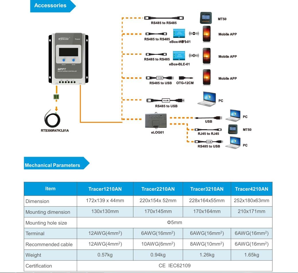
Image 5.2: Diagram showing the EPEVER solar charge controller and its compatible accessories. These include the RTS300R47K3.81A temperature sensor, MT50 remote meter, eBox-WIFI-01, eBox-BLE-01, OTG-12CM, and eLOG01 for various monitoring and communication options.

Image 5.3: The EPEVER Tracer2210AN solar charge controller connected to an MT50 remote meter, displaying system information. This setup allows for convenient monitoring and control.
6. メンテナンス
Regular maintenance ensures the longevity and optimal performance of your EPEVER solar charge controller:
- 接続を確認してください: 定期的にすべての配線接続部の締め付け具合と腐食を点検してください。接続が緩んでいると、電圧が上昇する可能性があります。tag落下や過熱を防ぎます。
- コントローラーをクリーニングします。 Keep the controller clean and free from dust and debris. Use a dry cloth to wipe the surface. Ensure ventilation openings are not blocked.
- 損傷の検査: Check for any physical damage to the controller, cables, or terminals.
- バッテリーの検査: For lead-acid batteries, check electrolyte levels (if applicable) and terminal condition. Ensure lithium batteries are within their recommended operating parameters.
- 環境条件: 設置環境が指定された動作温度および湿度の範囲内であることを確認してください。
7。 トラブルシューティング
If you encounter issues with your solar charge controller, refer to the following common troubleshooting steps:
- ディスプレイ/電源なし:
- バッテリーの接続を確認し、バッテリーの容量を確認してくださいtageはコントローラの動作範囲内です。
- バッテリーヒューズ(取り付けられている場合)が損傷していないことを確認します。
- ソーラーパネルからの充電なし:
- Ensure solar panel connections are secure and correct polarity is observed.
- Check the solar panel's open-circuit voltage (Voc) and short-circuit current (Isc) to ensure it is producing power.
- Verify that the solar panel voltage is within the controller's input voltage範囲。
- Check for shading on the solar panels.
- ロードが機能しない:
- 負荷接続を確認し、正しい極性を確保します。
- Verify that the battery has sufficient charge. The controller may disconnect the load if the battery voltageが低すぎます。
- Check load settings on the controller to ensure the load output is enabled.
- 過熱:
- Ensure the controller is installed in a well-ventilated area and its heat sinks are not obstructed.
- Reduce the load or solar input if operating in extreme temperatures.
For more detailed troubleshooting or specific error codes, please refer to the comprehensive manual provided by EPEVER or contact their customer support.
8. 仕様
The following table outlines the key electrical and mechanical parameters for the Tracer2210AN MPPT Solar Charge Controller:

Image 8.1: Table detailing the electrical parameters for Tracer series controllers, including the Tracer2210AN. This table provides specific values for system voltage, currents, power, and environmental conditions.
| パラメータ | 値 (Tracer2210AN) |
|---|---|
| システム公称容量tage | 12V/24V オートワーク |
| 定格充電電流 | 20A |
| 定格放電電流 | 20A |
| 最大PV入力電力 | 260W (12V Battery System) 520W (24V Battery System) |
| 最大。 PV開回路Voltage | 100V (at min. operating temp) 92V (at 25℃ ambient temp) |
| バッテリー巻tage範囲 | 8-32V |
| MPP ボリュームtage範囲 | V(BAT+2V) ~ 72V |
| 接地 | 共通のネガティブ |
| 追跡効率 | ≥99.5% |
| 最大変換効率 | 98% |
| 作業環境温度 | -25℃ ~ +50℃ |
| 保管温度範囲 | -20℃ ~ +70℃ |
| 相対湿度 | ≤95%、NC |
| 囲い | IP30 |
| 寸法(長さ×幅×高さ) | 220 x 154 x 52 ミリメートル |
| 重さ | 0.94キロ |
| 端子サイズ | #6 AWG (16 mm²) |
| 推奨ケーブル | #10 AWG (6 mm²) |
9. 保証とサポート
For warranty information, please refer to the documentation provided with your purchase or contact your authorized EPEVER dealer. EPEVER products typically come with a manufacturer's warranty covering defects in materials and workmanship.
For technical support, product inquiries, or service, please visit the official EPEVER website or contact an authorized EPEVER service center. Ensure you have your product model (Tracer2210AN) and serial number available when seeking support.