1. はじめに
The KELUSHI XQ-350 Wire Tracker is a versatile tool designed for telecommunication network line engineering, routine servicing, and computer network line maintenance. It assists in tracing wires, verifying LAN cable conditions, and performing continuity tests on various metal wire lines.
パッケージ内容
パッケージを開封したら、以下の品目がすべて揃っていることを確認してください。
- 1x Emitter Unit
- 1xレシーバーユニット
- イヤホン1個
- 1x RJ11 Adapter Cable
- 1x Alligator Clip Adapter Cable
- 1x RJ45 Adapter Cable
- ユーザーマニュアル (本書) x 1
- 1x Toolkit/Carrying Case

Figure 1.1: KELUSHI XQ-350 Wire Tracker and included accessories.

Figure 1.2: The carrying case and a list of its contents, ensuring all components are accounted for.
2. 製品の特徴と機能
The XQ-350 Wire Tracker offers a range of functionalities to assist in network and telephone cable management:
- 配線トレース: Locate telephone wires and LAN cables within electrical systems.
- LAN Cable Verification: Assess the condition of LAN cables, identifying open circuits, short circuits, and cross-connections.
- 導通テスト: Perform basic continuity checks on cables.
- 低バッテリー表示: バッテリー電力が少なくなるとユーザーに警告します。
- 内蔵LED懐中電灯: 暗い作業環境に照明を提供します。
- Cable Assignment Test: Specifically tests 2-wire (RJ11) and 4-wire (RJ45) telephone cables for open, short, and cross faults.
- Cable State Testing (2-wire): Detects DC line voltage, determines anode/cathode polarity, and identifies ringing signals.
- Target Wire Identification: Quickly find specific wires among bundles of telephone or network cables by comparing sound volume and signal indicator brightness.
- Ethernet Switch/Router Compatibility: Capable of finding wires connected to operating Ethernet switches, routers, or PC terminals.
3. コンポーネントの識別
3.1 Emitter Unit

図3.1: 前面 view of the Emitter unit with key components labeled.
The Emitter unit features:
- RJ11ポート: For connecting telephone cables.
- RJ45ポート: ネットワークケーブルを接続します。
- Wire Finding Indicator (STATUS): LEDs indicating the status during wire tracing.
- 機能切り替えボタン: Cycles through different test modes.
- 機能選択スイッチ: Toggles between SCAN, OFF, and TEST modes.
- Wire Sequence Indicator (1-8, G): LEDs that light up to show cable continuity and wiring sequence.
- Testing Indicator (VERIFY): Indicates the result of cable verification.
3.2 受信機

図3.2: 前面 view of the Receiver unit with key components labeled.
The Receiver unit features:
- プローブ: Used to detect the signal emitted by the Emitter.
- シグナルインジケーター: Visual indication of signal strength.
- Inching Button (PUSH TO TEST): Activates the signal detection.
- PWR-VOL Switch: Power and volume control for the receiver.
- ヘッドセットジャック: For connecting the included earphone for clearer audio detection.
- 音量調整器: オーディオ出力レベルを制御します。
- Spotlight Switch: 内蔵の LED 懐中電灯を点灯します。
- Wire Sequence Indicator (1-8, G): LEDs mirroring the Emitter's indicators during cable testing.
- RJ45ポート: For connecting network cables during testing.
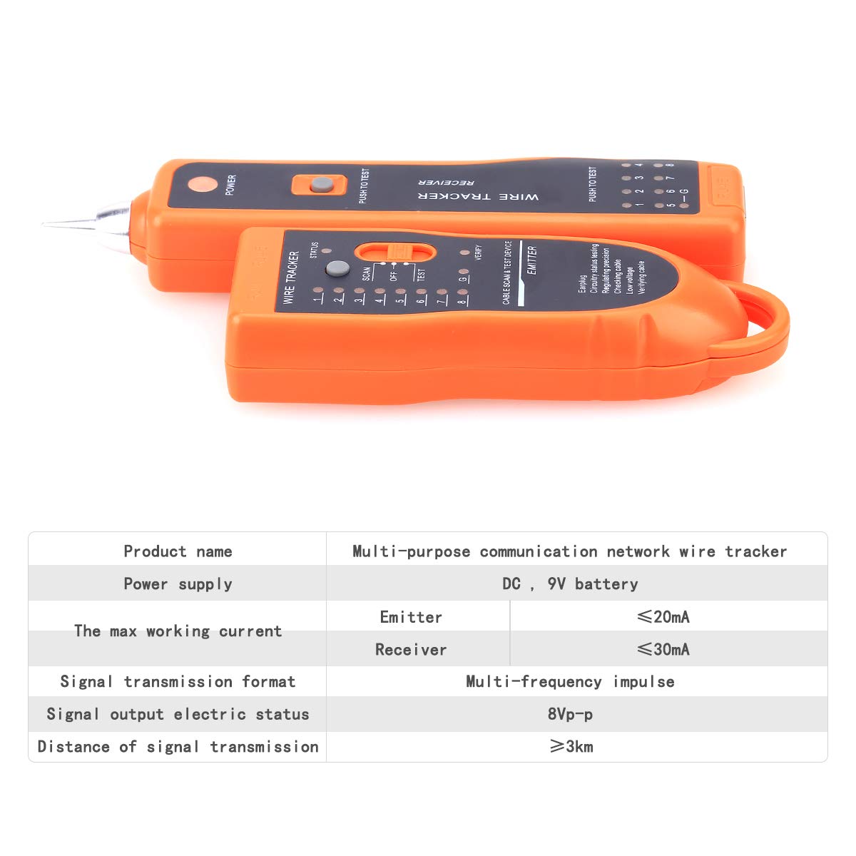
図3.3:詳細 views of the RJ45/RJ11 ports, probe, power switch, and speaker on the XQ-350 units.
4. セットアップ
4.1 バッテリーの取り付け
Both the Emitter and Receiver units require a 9V DC battery (not included) for operation.
- Locate the battery compartment cover on the back of each unit.
- カバーをスライドさせるかクリップを外してコンパートメントを開きます。
- 正しい極性を確認して、9V バッテリーをバッテリー クリップに接続します。
- バッテリーを収納部内に置き、カバーをしっかりと閉じます。

Figure 4.1: Open battery compartments of the Emitter and Receiver, showing where to insert the 9V laminated battery.
4.2接続ケーブル
Use the appropriate adapter cables (RJ45, RJ11, or alligator clips) to connect the Emitter to the cable you wish to test or trace. The Receiver is used to detect the signal or verify the cable status.
5. 操作手順
5.1 Wire Tracing (SCAN Mode)
This mode is used to locate a specific wire among a bundle of cables.
- Connect the Emitter to one end of the target cable using the appropriate adapter (RJ45, RJ11, or alligator clips).
- Set the Function Selector Switch on the Emitter to 'SCAN'. The 'STATUS' indicator will light up.
- Turn on the Receiver by adjusting the PWR-VOL switch. Adjust the volume to a comfortable level.
- Use the Receiver's probe to scan the cables at the other end or along the cable path.
- When the probe is near the target wire, the Receiver will emit an audible tone. The signal indicator LEDs will also light up.
- The target wire is identified by the loudest tone and brightest signal indicator.
- For clearer audio, connect the earphone to the Receiver's headset jack.
5.2 LAN Cable Testing (TEST Mode - RJ45)
This mode verifies the wiring sequence and identifies faults in RJ45 network cables.
- Connect one end of the RJ45 cable to the Emitter's RJ45 port and the other end to the Receiver's RJ45 port.
- Set the Function Selector Switch on the Emitter to 'TEST'.
- Observe the Wire Sequence Indicator LEDs (1-8, G) on both the Emitter and Receiver.
- 通常接続: LEDs on both units will light up sequentially from 1 to 8, then G (ground), indicating a correct wiring sequence.
- 開回路: If a specific LED (e.g., '3') does not light up on either unit, it indicates an open circuit on that wire.
- 短絡: If two or more LEDs light up simultaneously or out of sequence, it indicates a short circuit between those wires.
- Cross-Connection: If the sequence of LEDs on the Receiver differs from the Emitter, it indicates a cross-connection.
5.3 Telephone Cable Testing (TEST Mode - RJ11)
This mode is used for 2-wire telephone cables to check continuity and state.
- Connect one end of the RJ11 cable to the Emitter's RJ11 port using the RJ11 adapter.
- For cable state testing, connect the other end of the RJ11 cable to the line you wish to test.
- Set the Function Selector Switch on the Emitter to 'TEST'.
- Line DC Detecting and Anode/Cathode Determination: The Emitter will indicate the presence of DC voltage and its polarity.
- Ringing Signal Detecting: The Emitter can detect if a ringing signal is present on the line.
- Open, Short, and Cross Testing: Similar to LAN cable testing, the LEDs will indicate faults.
5.4 LED懐中電灯の使用
The Receiver unit includes a built-in LED flashlight for working in dimly lit areas.
- Locate the Spotlight Switch on the side of the Receiver unit.
- Slide the switch to the 'ON' position to activate the flashlight.
- 使用していないときは、スイッチを「OFF」の位置にスライドして、バッテリー寿命を節約してください。
6. メンテナンス
6.1 電池の交換
When the low battery indicator illuminates or the unit's performance degrades, replace the 9V battery in both the Emitter and Receiver units as described in Section 4.1.
6.2 清掃と保管
- Clean the units with a soft, dry cloth. Do not use abrasive cleaners or solvents.
- デバイスは直射日光や極端な温度を避け、涼しく乾燥した場所に保管してください。
- If storing for an extended period, remove the batteries to prevent leakage and damage to the device.
7。 トラブルシューティング
7.1 電源なし
- Ensure the 9V battery is correctly installed with proper polarity.
- バッテリーを新しいものと交換してください。
- Check that the power switch (PWR-VOL on Receiver, Function Selector on Emitter) is in the 'ON' or 'SCAN'/'TEST' position.
7.2 No Signal During Wire Tracing
- Verify the Emitter is set to 'SCAN' mode.
- Ensure the Emitter is properly connected to the cable.
- Adjust the Receiver's volume to maximum.
- Confirm the Receiver's probe is in close proximity to the target cable.
- Check for excessive electromagnetic interference in the environment.
7.3 Incorrect Cable Test Results
- Ensure both ends of the cable are securely connected to the Emitter and Receiver.
- Verify the Emitter is set to 'TEST' mode.
- Inspect the cable and connectors for visible damage.
- Test with a known good cable to confirm the device is functioning correctly.
8. 仕様
The following table outlines the technical specifications for the KELUSHI XQ-350 Wire Tracker:

Figure 8.1: Visual representation of the KELUSHI XQ-350 Wire Tracker's key specifications.
| パラメータ | 価値 |
|---|---|
| モデル | XQ-100 |
| 電源 | DC9Vバッテリー(別売り) |
| Working Current (Emitter) | ≤10mA (Test mode) |
| 動作電流(受信機) | ≤30mA |
| Signal Transmission Format | Multiple frequency pulse |
| Signal Output Electric Status | 8VP-P |
| Distance of Signal Transmission | ≥3km |
| 色 | オレンジ |
| 材料 | ABSプラスチック |
| エミッター寸法 | 約12.8×4.5×2.5cm |
| レシーバーの寸法 | 約17.5×4×2.2cm |
| アイテム重量 | 250グラム |
9. サポート
For any questions or assistance regarding the KELUSHI XQ-350 Wire Tracker, please contact the manufacturer or seller. Refer to your purchase documentation for specific contact details.