1. はじめに
This manual provides detailed instructions for installing, configuring, and maintaining your GIGABYTE GA-B150M-D3H Micro ATX motherboard. The GA-B150M-D3H is designed to support 6th Generation Intel Core Processors and features Dual Channel DDR4 memory, PCIe Gen3 x4 M.2 connector, SATA Express, and 8-channel HD audio with Audio Noise Guard.
Please read this manual thoroughly before beginning installation to ensure proper setup and operation.
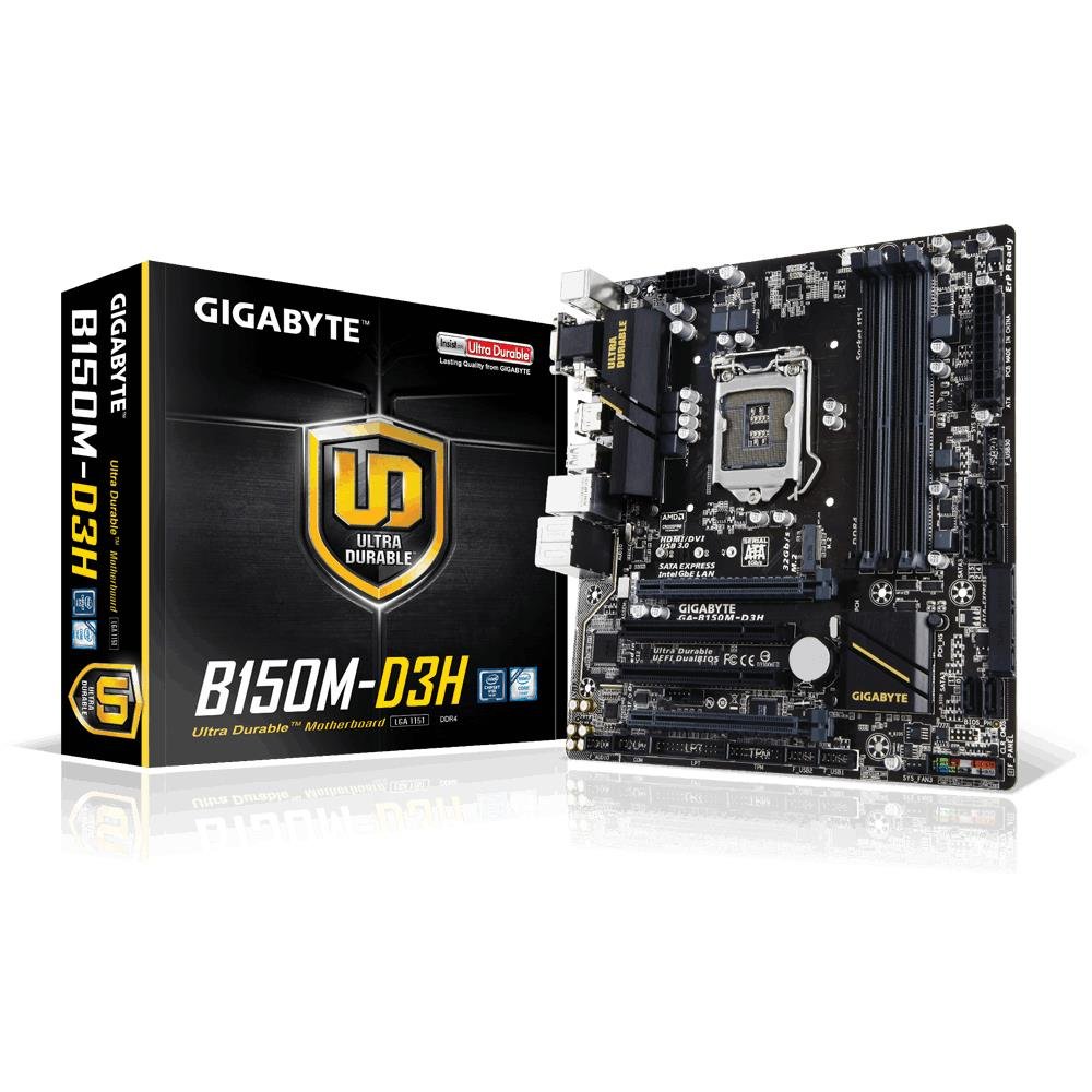
Image 1.1: GIGABYTE GA-B150M-D3H Micro ATX Motherboard. This image displays the overall layout of the motherboard, highlighting its compact Micro ATX form factor and various component slots.
2. 安全情報
マザーボードの損傷や怪我を防ぐために、次の安全上の注意事項を守ってください。
- コンポーネントに触れる前に、必ず電源コードを壁のコンセントから抜いてください。
- 静電気を放電するために、静電気防止リストストラップを着用するか、接地された金属物に頻繁に触れてください。
- 敏感なコンポーネントに触れないように、マザーボードの端を持ってください。
- マザーボードを湿気や極端な温度から遠ざけてください。
- 過熱を防ぐために、コンピューターケース内の換気が適切であることを確認してください。
3. パッケージ内容
マザーボード パッケージにすべてのアイテムが揃っていることを確認します。
- GIGABYTE GA-B150M-D3H Motherboard
- ユーザーマニュアル
- I / Oシールド
- SATAケーブル
- ドライバーCD/DVD
注意:地域や改訂により内容が若干異なる場合があります。
4. マザーボードのレイアウト
Familiarize yourself with the various components and connectors on the GA-B150M-D3H motherboard.
Image 4.1: GIGABYTE GA-B150M-D3H Motherboard Layout. This image provides a visual reference for the location of key components such as the CPU socket, DIMM slots, PCIe slots, SATA ports, and M.2 connector.
主要コンポーネント:
- LGA 1151 CPU ソケット: For 6th Generation Intel Core Processors.
- DDR4 DIMM Slots (4): Supports Dual Channel DDR4 memory up to 2133 MHz.
- PCIe スロット: Includes PCIe Gen3 x16 for graphics cards and PCIe x1 slots for expansion.
- M.2 コネクタ: Supports PCIe NVMe & SATA SSDs with up to 32Gb/s data transfer.
- SATA Express Connector: For up to 16Gb/s data transfer.
- SATA 6Gb/s ポート: 従来の SATA ストレージ デバイスを接続します。
- 24ピンATX電源コネクタ: 主電源入力。
- 8-Pin ATX 12V Power Connector: CPU電源入力。
- フロントパネルヘッダー: For power button, reset button, LED indicators, and USB ports.
- オーディオ コネクタ: 8-channel HD Audio with high quality capacitors and Audio Noise Guard.
5. セットアップとインストール
マザーボードとコンポーネントを適切にインストールするには、次の手順に従ってください。
5.1. CPUの取り付け
- Locate the LGA 1151 CPU socket.
- CPU ソケット レバーを開き、ロード プレートを持ち上げます。
- CPUをソケットに慎重に合わせ、CPUの金色の三角形がソケットの三角形と合っていることを確認してください。CPUをソケットに無理やり押し込まないでください。
- ロードプレートを下げてレバーで固定します。
5.2. CPUクーラーの取り付け
Refer to your CPU cooler's instruction manual for specific installation steps. Ensure thermal paste is applied correctly between the CPU and cooler base.
5.3. メモリ(RAM)の取り付け
- DDR4 DIMM スロットの両端のクリップを開きます。
- メモリ モジュールをスロットに合わせて、モジュールの切り込みがスロットのキーと一致していることを確認します。
- クリップがカチッと音がするまで、メモリ モジュールの両端をしっかりと押し下げます。
- For dual-channel performance, install memory modules in matching colored slots (e.g., DIMM1 and DIMM2).
5.4. 拡張カードの取り付け
- Remove the metal bracket from the desired PCIe slot on your computer case.
- Align the expansion card with the PCIe slot and press down firmly until it is seated correctly.
- カードをネジでコンピューターケースに固定します。
5.5. ストレージデバイスの接続
- SATA デバイス: Connect one end of the SATA data cable to a SATA 6Gb/s port on the motherboard and the other end to your hard drive or SSD. Connect the SATA power cable from your power supply to the device.
- M.2 SSD: M.2 SSD を M.2 スロットに斜めに挿入し、ゆっくりと押し下げて付属のネジで固定します。
- SATA Express: If using a SATA Express device, connect it to the designated SATA Express connector.
5.6. フロントパネルコネクタの接続
Connect the cables from your computer case's front panel (power button, reset button, HDD LED, power LED, front USB, front audio) to the corresponding headers on the motherboard. Refer to the motherboard layout diagram for exact locations and pin assignments.
5.7. 電源の接続
- 電源装置の 24 ピン ATX メイン電源コネクタをマザーボードの 24 ピン電源ソケットに接続します。
- Connect the 8-pin ATX 12V CPU power connector to the 8-pin socket near the CPU.
- すべての電源接続が安全であることを確認します。
6. 操作手順
6.1. 最初の起動
After assembling all components, connect your monitor, keyboard, and mouse. Power on the system. The system should display the GIGABYTE splash screen and then enter the BIOS/UEFI setup or attempt to boot from a connected storage device.
6.2. BIOS/UEFIセットアップ
BIOS/UEFIセットアップに入るには、 削除 key repeatedly during the boot process when the GIGABYTE logo appears. Here you can configure system settings, boot order, and monitor hardware status. The GA-B150M-D3H features GIGABYTE UEFI Dual BIOS for enhanced reliability.
6.3. ドライバーのインストール
After installing your operating system, install the necessary drivers for the motherboard components. These can be found on the included driver CD/DVD or downloaded from the official GIGABYTE website. Key drivers include chipset, audio (Realtek ALC892 codec), LAN, and any integrated graphics drivers.
6.4. オペレーティング システムのインストール
Insert your operating system installation media (USB drive or DVD) and configure the boot order in the BIOS/UEFI to boot from it. Follow the on-screen instructions to install your preferred operating system (e.g., Windows 8.1, Windows 10).
7. メンテナンス
7.1. 清掃
過熱の原因となるほこりの蓄積を防ぐため、コンピューターケース内部を定期的に清掃してください。ファン、ヒートシンク、マザーボードの部品に付着したほこりは、圧縮空気で除去してください。清掃前に、必ずシステムの電源を切り、電源プラグを抜いてください。
7.2. BIOSアップデート
GIGABYTEは、システムの安定性、互換性、パフォーマンスを向上させるため、定期的にBIOSアップデートをリリースしています。GIGABYTEの公式ウェブサイトをご覧ください。 website for your motherboard model (GA-B150M-D3H) to check for the latest BIOS version and follow the provided instructions for updating. Exercise caution during BIOS updates, as an interruption can render the motherboard inoperable.
8。 トラブルシューティング
このセクションでは、発生する可能性のある一般的な問題について説明します。
8.1. 電源が入らない / システムが起動しない
- 電源がマザーボードに正しく接続されているかどうかを確認します (24 ピンおよび 8 ピン コネクタ)。
- 電源スイッチがオンの位置にあることを確認します。
- フロントパネルの電源ボタン ケーブルがマザーボード ヘッダーに正しく接続されていることを確認します。
- 別のシステムまたは電源テスターを使用して電源をテストします。
8.2. ディスプレイ出力なし
- Ensure the monitor is connected to the correct graphics output (either integrated graphics on the motherboard or a dedicated graphics card).
- グラフィック カードとメモリ モジュールを装着し直します。
- メモリ モジュールを 1 つだけ取り付けた状態で起動してみます。
- モニターの電源がオンになっており、正しい入力ソースに設定されているかどうかを確認します。
8.3. システムの不安定性/クラッシュ
- CPU と GPU の温度をチェックして、安全な動作限度内であることを確認します。
- すべてのドライバーがインストールされ、最新であることを確認します。
- メモリ診断ツールを実行して、障害のある RAM がないか確認します。
- 電源がすべてのコンポーネントに十分かつ安定した電力を供給していることを確認します。
9. 仕様
Detailed technical specifications for the GIGABYTE GA-B150M-D3H motherboard:
| 特徴 | 仕様 |
|---|---|
| モデル名 | GA-B150M-D3H |
| フォームファクター | マイクロATX(24.4cm x 22.5cm) |
| CPUソケット | 1151 号線 |
| 互換性のあるプロセッサ | 第6世代Intel Coreプロセッサー |
| チップセット | Intel B150 Express チップセット |
| メモリ技術 | DDR4 |
| メモリスロット | 4 x DDR4 DIMM sockets (Dual Channel) |
| 最大メモリ容量 | 16ギガバイト |
| メモリクロック速度 | 2133 MHz |
| PCIeスロット | 1 x PCI Express x16, 1 x Total PCIe Ports |
| ストレージインターフェース | PCIe Gen3 x4 M.2, SATA Express, SATA 6Gb/s |
| オーディオコーデック | Realtek ALC892 codec, 8-channel HD Audio |
| USBポート | Total 8 USB Ports (including USB 2.0) |
| 主電源コネクタ | 24ピンATX |
| CPU電源コネクタ | 8-Pin ATX 12V |
| ユニークな機能 | GIGABYTE UEFI Dual BIOS, Audio Noise Guard with LED Trace Path Lighting, App Center (Easy Tune, Cloud Station) |
10. 保証とサポート
For warranty information, please refer to the warranty card included in your product package or visit the official GIGABYTE webサイトをご覧ください。保証条件は地域によって異なる場合があります。
For technical support, driver downloads, BIOS updates, and further product information, please visit the GIGABYTE official support webサイト:
https://www.gigabyte.com/Support
When contacting support, please have your motherboard model (GA-B150M-D3H) and serial number ready.