導入
This manual provides essential instructions for the installation, operation, maintenance, and troubleshooting of the IBM 49P1599 FRU System Board. This system board is designed for personal computers, featuring a 400/533 Front Side Bus, integrated 10/100 Ethernet, and support for DDR2 memory.
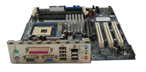
Image: The IBM 49P1599 FRU System Board. This image displays the main components and layout of the motherboard, including CPU socket, memory slots, and various connectors.
セットアップとインストール
Careful installation is crucial for the proper functioning of your system board. Always handle the board by its edges to avoid static discharge.
1.インストールの準備
- Ensure your computer case is compatible with the system board's form factor.
- 必要なツールを用意します: プラスドライバー、静電気防止リストストラップ。
- Unplug the power supply from the wall outlet before beginning.
2. Installing the System Board
- I/O シールドをコンピューター ケースの背面開口部に取り付けます。
- Carefully align the system board with the standoffs in the case.
- Secure the system board with screws, ensuring it is firmly seated.
3. コンポーネントのインストール
プロセッサ(CPU)
This system board is supplied without a processor. Refer to your CPU's manual for specific installation instructions. Ensure the CPU is correctly oriented in the socket before securing the retention lever.
メモリ(RAM)
The board supports DDR2 RAM and has 2 memory slots.
- メモリスロットの両端のクリップを開きます。
- メモリ モジュールをスロットに合わせて、モジュールの切り込みがスロットのキーと一致していることを確認します。
- クリップがカチッと音がするまで、モジュールの両端をしっかりと押し下げます。
グラフィックカード
The system board features an Integrated Graphics Card Interface and a PCI-Express x16 slot for dedicated graphics cards.
- PCI-Express x16 スロットを見つけます。
- Remove the corresponding expansion slot cover from your case.
- Insert the graphics card firmly into the slot until it clicks. Secure it with a screw to the case.
4. ケーブルの接続
- 電源コネクタ: Connect the main 24-pin ATX power connector and the 4-pin CPU power connector from your power supply to the system board.
- SATA デバイス: Connect SATA 3 data cables from your storage devices (hard drives, SSDs) to the SATA ports on the system board.
- フロントパネルコネクタ: Connect the power button, reset button, HDD LED, power LED, and USB ports from your case to the corresponding headers on the system board. Refer to the board's silkscreen labels for correct orientation.
- イーサネット: The board has integrated 10/100 Ethernet. Connect your network cable to the RJ-45 port on the I/O panel.
操作手順
After completing the physical installation, you can proceed with the initial boot and operating system setup.
1. 初期ブート
- すべてのコンポーネントがしっかりと接続されていることを確認してください。
- モニター、キーボード、マウスを接続します。
- Plug in the power supply and turn on the system.
- システムの電源が入り、モニターに画面が表示されます。
2. BIOS/UEFIセットアップ
During the initial boot sequence, press the designated key (commonly DEL, F2, F10, or F12) to enter the BIOS/UEFI setup utility. Here you can configure boot order, system time, and other hardware settings. Save changes before exiting.
3. オペレーティング システムのインストール
This system board is compatible with platforms such as Windows 10. Insert your operating system installation media (USB drive or DVD) and follow the on-screen prompts to install the operating system. Ensure all necessary drivers for the system board components are installed after the OS installation.
メンテナンス
Regular maintenance helps ensure the longevity and stable performance of your system board.
- クリーニング: Periodically clean dust from the system board and components using compressed air. Ensure the system is powered off and unplugged before cleaning.
- BIOS アップデート: Check the official IBM support website for BIOS updates. BIOS updates can improve compatibility, stability, and performance. Follow the provided instructions carefully when updating the BIOS.
- コンポーネントチェック: Ensure all cables and components remain securely connected.
トラブルシューティング
問題が発生した場合は、次の一般的なトラブルシューティング手順を参照してください。
電源なし
- Verify the power supply is connected to the wall outlet and turned on.
- Check that the 24-pin and 4-pin power connectors are securely attached to the system board.
- Ensure the front panel power button cable is correctly connected to the system board header.
表示なし
- Confirm the monitor is powered on and connected to the correct video output (either integrated or dedicated graphics card).
- グラフィック カード (該当する場合) とメモリ モジュールを装着し直します。
- 可能であれば、別のモニターまたはビデオ ケーブルでテストしてください。
システムの起動に失敗する
- Check for any loose cables or components.
- Ensure the CPU is properly seated and its cooler is installed correctly.
- Try booting with only one memory module installed, rotating through the modules and slots to identify a faulty one.
- Reset the BIOS to default settings (refer to your system board's specific instructions for clearing CMOS).
仕様
保証とサポート
For warranty information and technical support, please refer to the official IBM website or contact your point of purchase. Keep your proof of purchase for warranty claims. IBM provides resources and support for its products to ensure customer satisfaction.
さらにサポートが必要な場合は、次のサイトを参照してください。 IBMサポート webサイト.
Ask a question about this manual
Ask about setup, troubleshooting, compatibility, parts, safety, or missing instructions. Manuals+ will review the question and use this page’s manual context to help answer it.
Posting as .
| 特徴 | 仕様 |
|---|---|
| モデル番号 | 49P1599 FRU |
| フロントサイドバス(FSB) | 400/533MHz |
| RAMメモリ技術 | DDR2 |
| メモリクロック速度 | 2133 MHz |
| 利用可能なメモリスロット | 2 |
| グラフィックカードインターフェース | 統合型 PCI-Express x16 |
| サポートされているシステムバス規格 | SATA3 について |
| Integrated Ethernet | 10/100 Mbps |
| 対応デバイス | パソコン |
| プラットフォームの互換性 | ウィンドウズ10 |
| アイテム重量 | 8ポンド |